VLT
®
6000 HVAC
Installation
d[mm] Comments
Bookstyle
VLT 6002-6005, 200-240 V 100
VLT 6002-6011, 380-460 V 100
Installation on a plane, vertical surface (no spacers)
Compact (all enclosure types)
VLT 6002-6005, 200-240 V 100
VLT 6002-6011, 380-460 V 100
VLT 6002-6011, 525-600 V 100
Installation on a plane, vertical surface (no spacers)
VLT 6006-6032, 200-240 V 200
VLT 6016-6072, 380-460 V 200
VLT 6102-6122, 380-460 V 225
VLT 6016-6072, 525-600 V 200
Installation on a plane, vertical surface (no spacers)
VLT 6042-6062, 200-240 V 225
VLT 6100-6275, 525-600 V 225
Installation on a plane, vertical surface (no spacers)
IP 54 filter mats must be changed when they are dirty.
VLT 6152-6352, 380-460 V 225 Installation on a plane, vertical surface (spacers can be used). IP 54 filter
mats must be changed when they are dirty.
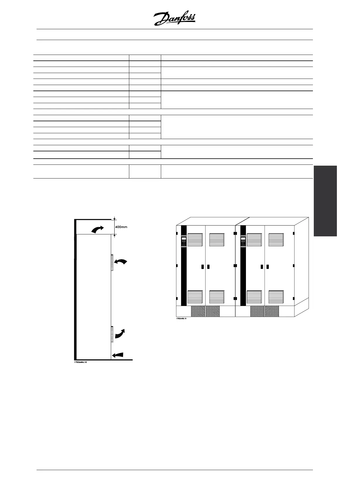
■ Installation of VLT 6400-6550 380-460 V Compact
IP 00, IP 20 and IP 54
Cooling Side-by-side
All units in the above-mentioned series require a
minimum spac
e of 400 mm above the enclosure
and must be installed on a plane floor. This applies
to both IP 00, IP 20 and IP 54 units.
Gaining acce
ss to VLT 6400-6550 requires a
minimum space of 605 mm in front of the frequency
converter.
All IP 00, IP 20 and IP 54 units in the
above-menti
oned series can be installed side by side
without any space between them, since these units
do not require cooling on the sides.
■ IP 00 VLT 6400-6550 380-460 V
The IP 00 unit is designed for installation in a cabinet
when installed according to the instructions in the
VLT 6400-6550 Installation Guide MG.56.AX.YY.
Please note, that the same conditions as for NEMA
1/ IP20 and IP54 must be fulfilled.
MG.60.C7.02 - VLT is a registered Danfoss trademark
5

 Loading...


