VLT
®
6000 HVAC
■ Electrical installation, control cables
Max. control cable cross section: 1.5 mm
2
/16 AWG
Torque: 0.5-0.6 Nm
Screw size: M3
See Earthing of screened/armoured control cables
for correct termination of control cables.
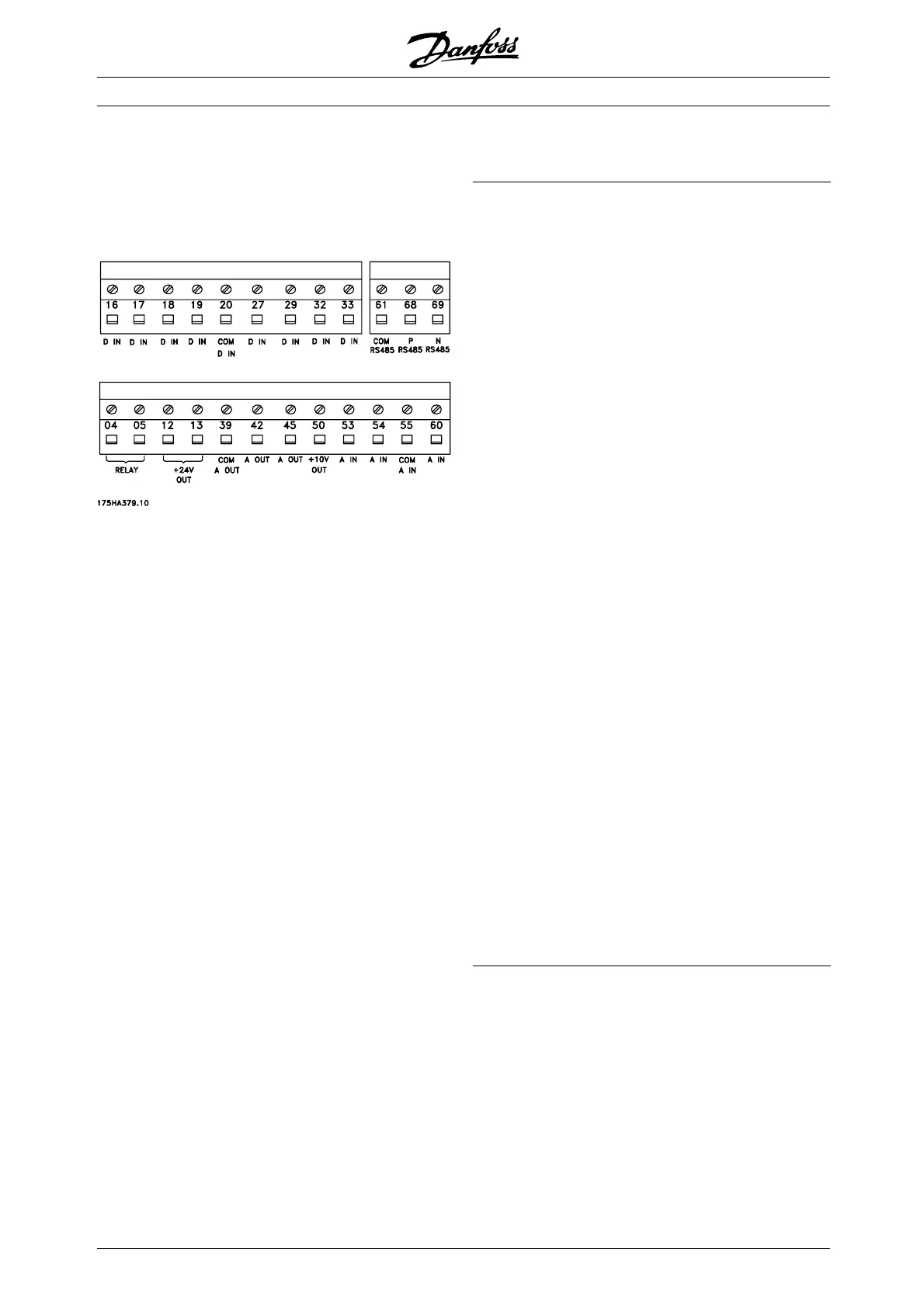
No. Function
04, 05 Relay output 2 can be used for indicating
status and warnings.
12, 13 Voltage supply to digital inputs. For the 24 V
DC to be used for digital inputs, switch 4 on
the control card must be closed, position "on".
16-33 Digital inputs. See parameters 300-307 Digital
inputs.
20 Ground for digital inputs.
39 Ground for analogue/digital outputs. Must
be connected to terminal 55 by means of
a three-wire transmitter. See Examples of
connection.
42, 45 Analogue/digital outputs for indicating
frequency, reference, current and torque. See
parameters 319-322 Analogue/d igital outputs.
50 Supply voltage to potentiometer and thermistor
10 V DC.
53, 54 Analogue voltage input, 0 - 10 V DC.
55 Ground for analogue voltage inputs.
60 Analogue current input 0/4-20 mA. See
parameters 314-316 Terminal 60.
61 Termination of serial communication. See
Earthing of screened/armoured control cables.
This terminal is not normally to be used.
68, 69 RS 485 interface, serial communication.
Where the frequency converter is connected
to a bus, switches 2 and 3 (switches 1- 4 -
see next page) must be closed on the first
and the last frequency converter. On the
remaining frequency converters, switches 2
and 3 must be open. The factory setting is
closed (position on).
MG.60.C7.02 - VLT is a registered Danfoss trademark
16

 Loading...


