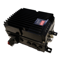
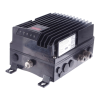
VLT
®
FCD Series
■ Contents
Introduction to FCD 300
................................................................................ 3
Software version ...................................................................................................... 3
High voltage warning ............................................................................................... 4
These rules concern your safety ............................................................................... 4
Warning against unintended start ............................................................................. 4
Installation ........................................................................................................... 7
Mechanical measurements ..................................................................................... 7
Mechanical dimensions, FCD, motor mounting ........................................................ 7
Mechanical dimensions, stand alone mounting ........................................................ 7
Mechanical installation ............................................................................................. 8
General information about electrical installation ...................................................... 10
Electronics purchased without installation box ....................................................... 10
EMC-correct electrical installation .......................................................................... 11
Diagram ................................................................................................................. 13
RFI switches J1, J2 ................................................................................................ 13
Location of terminals .............................................................................................. 14
Mains connection ................................................................................................... 16
Pre-fuses ................................................................................................................ 16
Motor connection ................................................................................................... 16
Direction of motor rotation ..................................................................................... 16
Mains and motor connection with service switch ................................................... 16
Connection of HAN 10E motor plug for T73 .......................................................... 16
Parallel connection of motors ................................................................................. 17
Motor cables .......................................................................................................... 17
Motor thermal protection ....................................................................................... 17
Brake resistor ......................................................................................................... 17
Control of mechanical brake .................................................................................. 18
Electrical installation, control cables ....................................................................... 19
Connection of sensors to M12 plugs for T53, T63, T73 ........................................ 20
Electrical installation, control terminals ................................................................... 21
PC communication ................................................................................................ 21
Relay connection ................................................................................................... 21
Connection examples ............................................................................................ 22
Programming, FCD 300 ............................................................................... 26
The LCP 2 control unit, option ............................................................................... 26
Parameter selection ............................................................................................... 29
Operation & Display ............................................................................................... 31
Setup configuration ................................................................................................ 31
Load and Motor ..................................................................................................... 39
DC Braking ............................................................................................................ 43
Motortype, par, 147 - FCD 300 ............................................................................. 48
References & Limits ............................................................................................... 49
Handling of references ........................................................................................... 49
Reference function ................................................................................................. 53
Inputs and outputs ................................................................................................. 57
Special functions .................................................................................................... 66
PID functions ......................................................................................................... 68
Handling of feedback ............................................................................................. 70
Serial communication for FCD 300 ........................................................................ 77
MG.04.B7.02 - VLT is a registered Danfoss trademark
1


 Loading...