VLT
®
FCD Series
Description of choice:
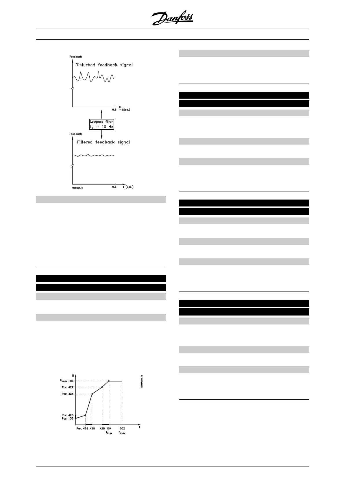
If a time constant (t) of 100 ms is programmed, the
cut-off frequency for the lowpass filter will be 1/0.1 =
10 RAD/sec., corresponding to (10 / 2 x π)=1.6Hz.
The PID regulator will then only regulate a feedback
signal that varies with a frequency of less than 1.6 Hz.
If the feedback signal varies by a higher frequency than
1.6 Hz, it will be dampened by the lowpass filter.
423 U1 voltage
(U1 VOLTAGE)
Value:
0.0 - 999.0 V
✭ par. 103
Function:
Parameters 423-428 are used when in parameter
101 Torque characterist i c a selection has be
en made
of Special motor characteristic [8]. It is possible to
determine a U/f characteristic on the basis of four
definable voltages and three frequencie
s. The voltage
at 0 Hz is set in parameter 133 Start voltage.
Description of choice:
Set the output voltage (U1) that is to match the first
output frequency (F1), parameter 424 F1 frequency.
424 F1 frequency
(F1 FREQUENCY)
Value:
0.0 - par. 426 F2 frequency
✭ Par. 104 Motor frequency
Function:
See parameter 423 U1 voltage .
Description of choice:
Set the output frequency (F1) that is to match the first
output voltage (U1), parameter 423 U1 voltage .
425 U2 voltage
(U2 VOLTAGE)
Value:
0.0 - 999.0 V
✭ par. 103
Function:
See parameter 423 U1 voltage.
Description of choice:
Set the output voltage (U2) that is to match the second
output frequency (F2), parameter 426 F2 frequency.
426 F2 frequency
(F2 FREQUENCY)
Value:
Par. 424 F1 frequency - par. 428 F3 frequency
✭ Par. 104 Motor frequency
Function:
See parameter 423 U1 voltage.
Description of choice:
Set the output frequency (F2) that is to match the
second output voltage (U2), parameter 425 U2 voltage .
✭ = factory setting. () = display text [] = value for use in communication via serial communication port
MG.04.B7.02 - VLT is a registered Danfoss trademark
72
 Loading...


