VLT
®
FCD Series
Par. 200 Output frequency range = Both direc-
tions, 0-132 Hz [1]
Par. 203 Reference range = Min. ref. - Max. ref.
[0]
Par. 204 Min. reference = - 50 Hz
Par. 205 Max. reference =50Hz
Par. 302 Digital input = Start [7]
Par. 304 Digital input = Coasting stop inverted [2]
Par. 308 Analogue input = Reference [1]
Par. 309 Terminal 53, min. scaling = 0 Volt.
Par. 310 Terminal 53, max. scaling = 10 Volt.
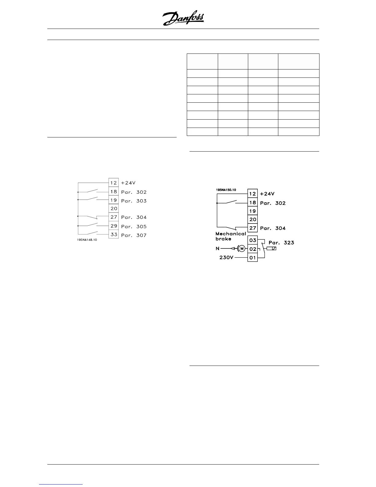
■ Preset references
Switch between 8 preset references via two digital
inputs and Setup 1 and Setup 2.
Par. 004 Active Setup = Multisetup 1 [5]
Par. 204 Min. reference =0Hz
Par. 205 Max. reference =50Hz
Par. 302 Digital input = Start [7]
Par. 303 Digital input = Choice of Setup, lsb [31]
Par. 304 Digital input = Coasting stop inverted [2]
Par. 305 Digital input = Preset ref., lsb [22]
Par. 307 Digital input = Preset ref., msb [23]
Setup 1 contains the following preset references:
Par. 215 Preset reference 1 = 5.00%.
Par. 216 Preset reference 2 = 10.00%.
Par. 217 Preset reference 3 = 25.00%.
Par. 218 Preset reference 4 = 35.00%.
Setup 2 contains the following preset references:
Par. 215 Preset reference 1 = 40.00%.
Par. 216 Preset reference 2 = 50.00%.
Par. 217 Preset reference 3 = 70.00%.
Par. 218 Preset reference 4 = 100.00%.
This table shows what the output frequency is:
Preset
ref., msb
Preset
ref., lsb
Selection
of Setup
Output fre-
quency[Hz]
0 0 0 2.5
0 1 0 5
1 0 0 10
1 1 0 17.5
0 0 1 20
0 1 1 25
1 0 1 35
1 1 1 50
■ Connection of mechanical brake
Use of the relay for 230V AC brake
Par. 302 Digital input = Start [7]
Par. 304 Digital input = Coasting stop inverted [2]
Par. 323 Relay output = Mechanical brake control
[25]
Mechanical brake control [25] = ’0’ => Brake is
closed.
Mechanical brake control [25] = ’1’ => The brake is
open.
See more detailed parameter settings under Control
of mechanical brake.
■ Counter stop via terminal 33.
The start signal (terminal 18) must be active, i.e.
logical ’1’, until the output frequency is equal to the
reference. The start signal (terminal 18 = logical ’0’)
must then be removed before the counter value in
parameter 344 has managed to stop the VLT fre-
quency converter.
MG.04.A1.02 - VLT is a registered Danfoss trade mark
46
 Loading...


