VLT
®
FCD Series
Description of choice:
Set the required time.
127
127 DC brake cut-in frequency
(DC BRAKE CUT-IN)
Value:
0.0 (OFF) - par. 202
Output frequency high limit, f
MAX
✭ OFF
Function:
In this parameter, the DC brake cut-in frequency is
set at which the DC brake is to be activated in con-
nection with a stop command.
Description of choice:
Set the required frequency.
128
128 Thermal motor protection
(MOT.THERM PROTEC)
Value:
✭No protection (NO PROTECTION)
[0]
Thermistor warning
(THERMISTOR WARN)
[1]
Thermistor trip (THERMISTOR TRIP)
[2]
ETR warning 1 (ETR WARNING 1)
[3]
ETR trip 1 (ETR TRIP 1)
[4]
ETR warning 2 (ETR WARNING 2)
[5]
ETR trip 2 (ETR TRIP 2)
[6]
ETR warning 3 (ETR WARNING 3)
[7]
ETR trip 3 (ETR TRIP 3)
[8]
ETR warning 4 (ETR WARNING 4)
[9]
ETR trip 4 (ETR TRIP 4)
[10]
Function:
The frequency converter can monitor the motor tem-
perature in two different ways:
- Via a PTC thermistor that is mounted on the mo-
tor. The thermistor is connected between terminal
31a / 31b. See parameter 300 Digital inputs.
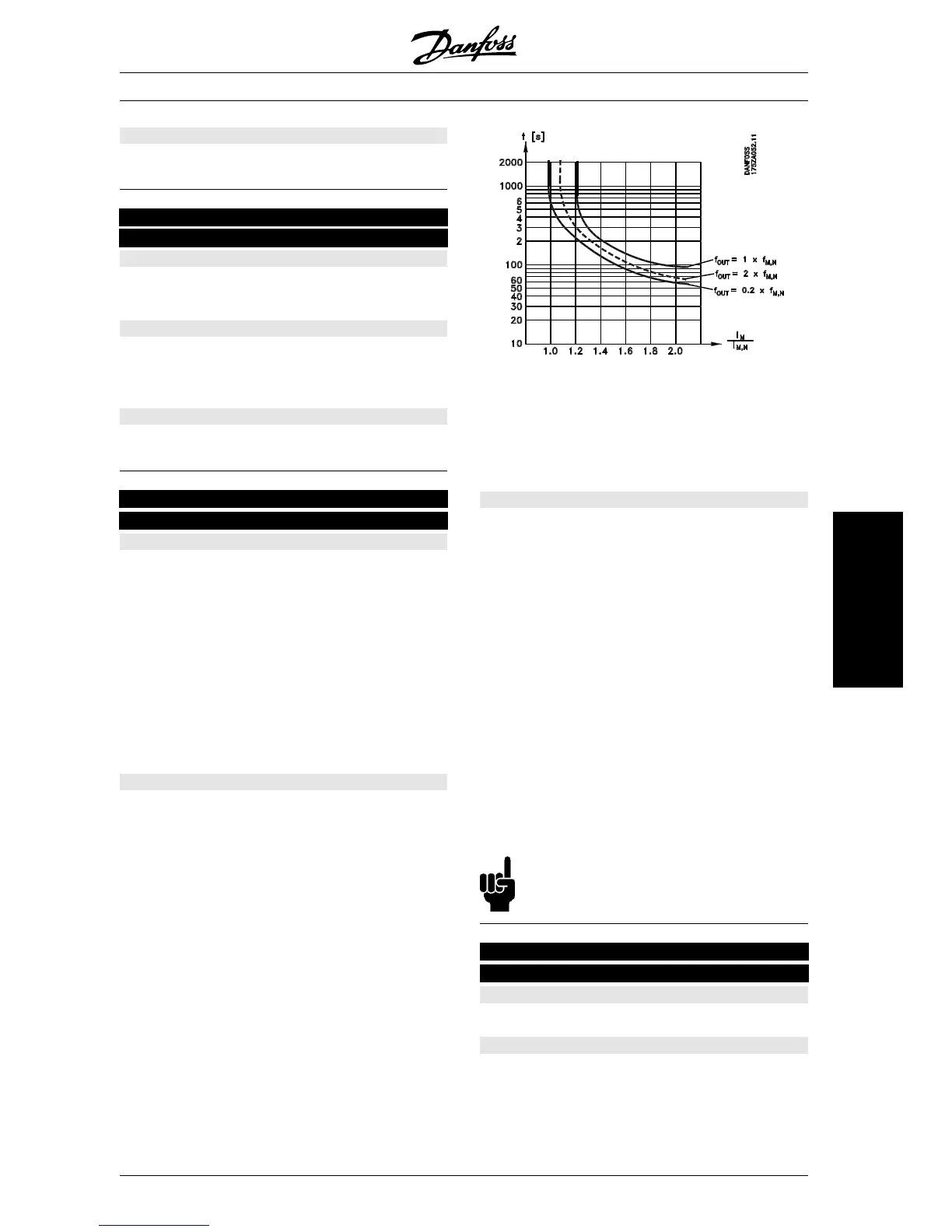
- Thermal load calculation (ETR - Electronic Ther-
mal Relay), based on present load and time. This
is compared with the rated motor current I
M,N
and
rated motor frequency f
M,N
. The calculations take
into account the need for lower loading at low
speeds due to the motor’s internal ventilation be-
ing reduced.
ETR functions 1-4 do not begin to calculate the load
until you switch to the Setup in which they have
been selected. This means that you can use the
ETR function even when changing between two or
more motors.
Description of choice:
Select No protection [0] if you do not want a warning
or trip when a motor is overloaded.
Select Thermistor warning [1] if you want a warning
when the connected thermistor becomes too hot.
Select Thermistor trip [2] if you want a trip when the
connected thermistor becomes too hot.
Select ETR Adv. if you want a warning when the
motor is overloaded according to the calculations.
You can also programme the frequency converter to
give a warning signal via the digital output.
Select ETR Trip if you want a trip when the motor is
overloaded according to the calculations.
Select ETR warning 1-4 if you want a warning when
the motor is overloaded according to the calculations.
You can also programme the frequency converter to
give a warning signal via one of the digital outputs.
Select ETR Trip 1-4 if you want a trip when the mo-
tor is overloaded according to the calculations.
NB!:
This function cannot protect the individual
motors in the case of motors linked in parallel.
130
130 Start frequency
(START FREQUENCY)
Value:
0.0 - 10.0 Hz
✭ 0.0 Hz
Function:
The start frequency is active for the time set in pa-
rameter 120 Start delay, after a start command. The
output frequency will ’jump’ to the next preset fre-
quency. Certain motors, such as conical anchor
motors, need an extra voltage/start frequency
✭
= factory setting. () = display text [] = value for use in communication via serial communication port
MG.04.A1.02 - VLT is a registered Danfoss trade mark
61
Programming
 Loading...


