this cable to both the decoupling plate and the
motor.
•
Keep the motor cable as short as possible to
reduce the noise level and leakage currents.
•
For further details on mounting the decoupling
plate, see FC 101 De-coupling Plate Mounting
Instruction.
•
Also see EMC-Compatible Installation in the FC 101
Design Guide.
1. Mount the ground cables to the ground terminal.
2. Connect the motor to terminals U, V, and W, and
tighten the screws according to the torques
specified in chapter 3.2.1 Electrical Installation in
General.
3. Connect the line power supply to terminals L1,
L2, and L3, and tighten the screws according to
the torques specified in chapter 3.2.1 Electrical
Installation in General.
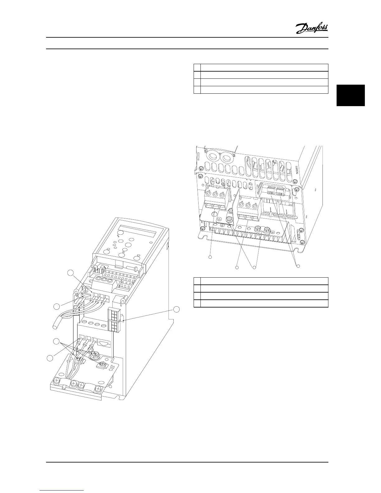
Relays and terminals on H1-H5 enclosures
1 Line power
2 Ground
3 Motor
4 Relays
Figure 3.3 H1–H5 Enclosures
IP20, 200-240 V, 0.25–11 kW (0.33–15 HP)
IP20, 380-480 V, 0.37–22 kW (0.5–30 HP)
Relays and terminals on H6 enclosure
1 Line power
2 Motor
3 Ground
4 Relays
Figure 3.4 H6 Enclosure
IP20, 380-480 V, 30-45 kW (40-60 HP)
IP20, 200-240 V, 15-18.5 kW (20-25 HP)
IP20, 525-600 V, 22-30 kW (30-40 HP)
Installation Quick Guide
MG18A622 Danfoss A/S © 08/2014 All rights reserved. 11
3 3

 Loading...


