130BA262.10
M
I N S
+DC
BR-
BR+
U
V
W
RELAY 1 RELAY 2
95
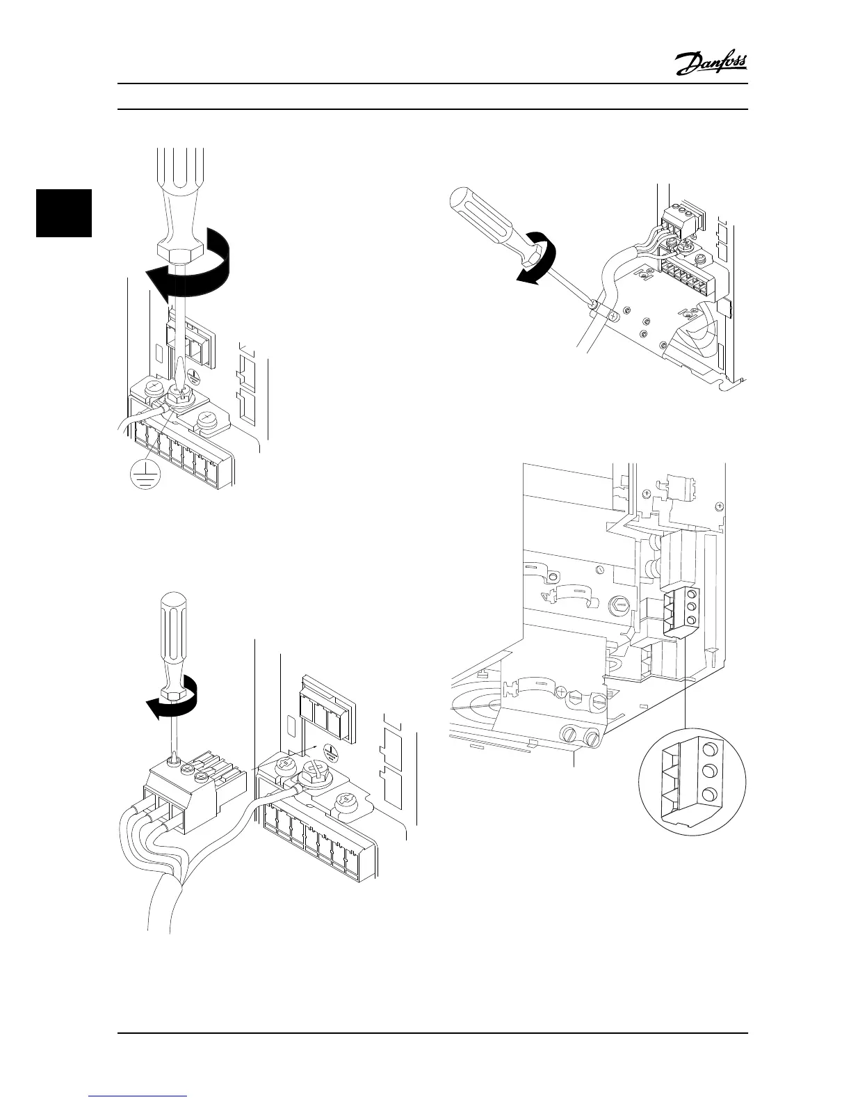
Figure 3.9 Mounting the Ground Cable
3. Insert the line cables to the line power plug and
tighten the screws, as shown in Figure 3.10.
130BA263.10
95
M
A
INS
+DC
BR-
BR+
U
V
W
91
92
93
L1
L2
L3
RELAY 1 RELAY 2
Figure 3.10 Mounting the Line Power Plug
4. Mount the support bracket across the line cables
and tighten the screws, as shown in Figure 3.11.
+DC
BR-
BR+
U
V
W
MAINS
L1 L2 L3
91 92 93
RELAY 1 RELAY 2
99
- LC -
130BA264.10
Figure 3.11 Mounting the Support Bracket
Relays and terminals on H10 enclosure
Figure 3.12 H10 Enclosure
IP20, 600 V, 11-15 kW (15-20 HP)
Installation VLT®HVAC Basic Drive FC 101
14 Danfoss A/S © 08/2014 All rights reserved. MG18A622
33

 Loading...


