EasyManuals Logo

Danfoss VLT HVAC Drive FC 102 Installation Instructions

Danfoss VLT HVAC Drive FC 102
10 pages
To Next Page IconTo Next Page
To Previous Page IconTo Previous Page
Page #5 background imageLoading...
Page #5 background image
Pressure Signals on Outputs
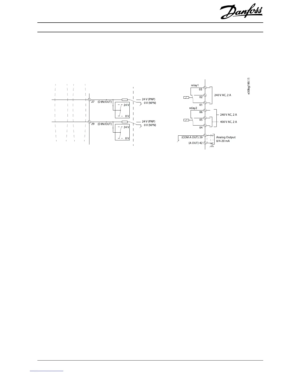
The frequency converter can be congured to transmit the pressure values on analog output or active status on digital and relay
outputs. Perform the
conguration
in parameter group 5-** Main Menu - Digital In/Out and parameter group 6-** Main Menu - Analog
In/Out. See the wiring diagram in Illustration 1.6.
Illustration 1.6 Wiring Diagram
Installation Instructions
Pressure Transmitter Unit PTU 025
VLT
®
HVAC Drive FC 102
MI08A102 Danfoss A/S © 12/2017 All rights reserved.
5

Other manuals for Danfoss VLT HVAC Drive FC 102

Questions and Answers:

Question and Answer IconNeed help?

Do you have a question about the Danfoss VLT HVAC Drive FC 102 and is the answer not in the manual?

Danfoss VLT HVAC Drive FC 102 Specifications

General IconGeneral
EnclosureIP20, IP21, IP55
Ambient Temperature Range-10°C to +40°C
Storage Temperature Range-25°C to +70°C
Relative Humidity5-95% (non-condensing)
Communication ProtocolsModbus RTU, BACnet, Profibus
CertificationsCE, UL, cUL
Control PrinciplePWM
Cooling MethodForced air cooling
Input Voltage200-240V, 380-480V, 525-600V
Control Modessensorless vector control, closed loop vector control

Related product manuals