14
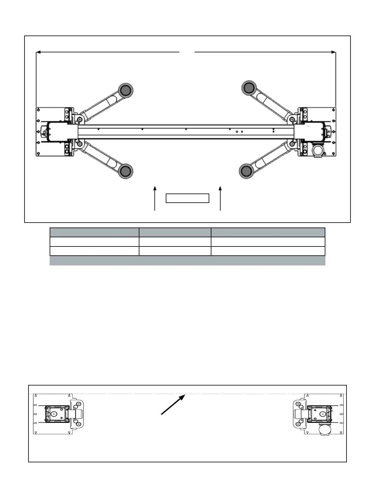
FLOOR PLAN
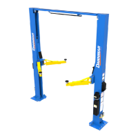
Model A Capacity
D2-12C 155.25” / 3,941 mm 12,000 lbs
D2-15C 155.25” / 3,941 mm 15,000 lbs
APPROACH
A
STEP 4
(Site Layout)
1. Determine which side of the Lift will be the approach
side.
2. Determine where the Power Unit will be located. The
Powerside Post has the Power Unit Mounting Bracket
attached to the side.
3. Determine which lift width layout you would like to use.
4. Once a location is determined, use chalk line to
layout an alignment line for the Post locations.
Keep all dimensions square within 1/8” (3 mm) or
malfunctioning of the lift can occur. (See Fig 4.1)
5. After the Post locations are properly marked, make an
outline of the posts on the oor at each Column location
using the Column base plates as a template.
6. VERIFY ALL DIMENSIONS and make sure that the
layout is perfectly square.
Fig 4.1.
USE BASE PLATE EDGES TO ALIGN POSTS
CHALK LINE