15
STEP 5
(Installing The POWERSIDE Column)
1. Before proceeding, review your measurements and
ensure that the Column Base Plates are aligned with the
chalk line.
2. Using the Base Plate on the POWERSIDE column as a
guide, drill each anchor hole in the concrete approximately
6” deep using a rotary hammer drill and 3/4” concrete drill-
bit. Do not ream the hole or allow the drill to wobble.
3. After drilling, remove dust thoroughly from each hole
making certain that the Column remains aligned with the
chalk line.
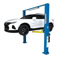
4. Assemble the Washers and Nuts on the anchors then
tap into each hole with a hammer until the washer rests
against the Base Plate. Be sure that if shimming is required
that enough threads are left exposed. (See Fig. 5.2)
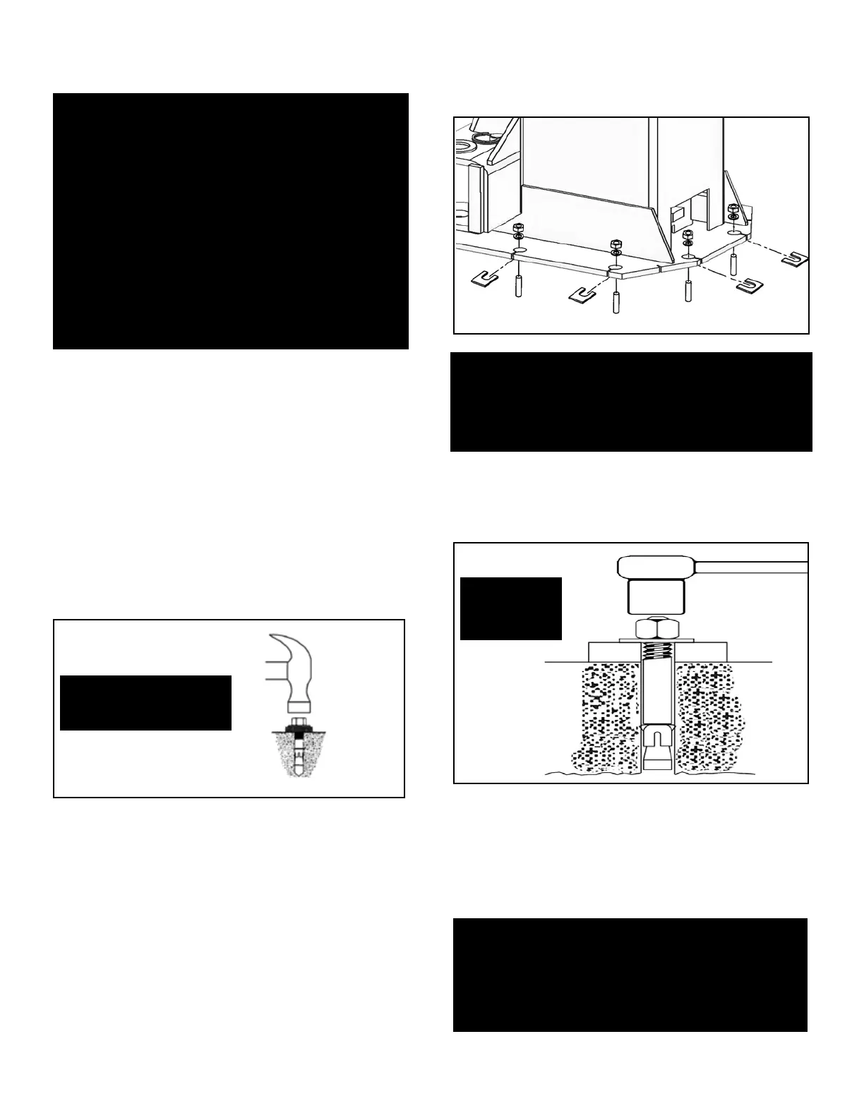
5. Insert the shims as necessary under the Base Plate so
that when the anchor bolts are tightened, the Columns will
be plumb. (See Fig. 5.3)
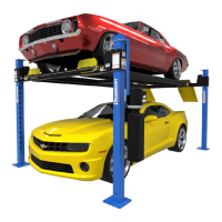
6. With the shims and anchor bolts in place, tighten by
securing the nut to the base then turning 3-5 full turns
clockwise. DO NOT use an impact wrench for this
procedure. (See Fig. 5.4)
STEP 6
(Mounting The OFFSIDE Column)
1. Position the OFFSIDE Column at the chalk line location
and secure to the oor following the same instructions as
outlined in the previous procedure (Steps 1-6).
Fig 5.3
NOTE:
DANNMAR LIFTS ARE SUPPLIED WITH INSTALLATION
INSTRUCTIONS AND CONCRETE FASTENERS
MEETING THE CRITERIA AS PRESCRIBED BY THE
LATEST VERAMERICAN NATIONAL STANDARD "
AUTOMOTIVE LIFTS - SAFETY REQUIREMENTS FOR
CONSTRUCTION, TESTING, AND VALIDATION"
ANSI/ALI ALCTV-2011. LIFT BUYERS
SHOULD CONTACT QUALIFIED PERSONS
REGARDING ANY SPECIAL REGIONAL,
STRUCTURAL AND/OR SEISMIC ANCHORING
REQUIREMENTS SPECIFIED BY ANY OTHER
AGENCIES AND/OR CODES SUCH AS THE UNIFORM
BUILDING CODE (UBC) AND/OR INTERNATIONAL
BUILDING CODE (IBC).
NOTE:
TO EASE INSTALLATION OF THE OVERHEAD
ASSEMBLY, IT HELPS TO KEEP THE ANCHOR
BOLTS LOOSE ON ONE OF THE POSTS UNTIL THE
OVERHEAD ASSEMBLY IS MOUNTED.
Fig 5.2
Tap anchor bolts into
each hole with a hammer
until the washer rests against
the baseplate.
Fig 5.4
Tighten Nut
3- Turns.
Do Not Use
Impact Wrench.
NOTE:
TO EASE THE INSTALLATION OF THE OVERHEAD
ASSEMBLY, IT HELPS TO KEEP THE ANCHOR BOLTS
LOOSE ON ONE OF THE POSTS UNTIL THE
OVERHEAD ASSEMBLY IS MOUNTED.