D4-9 / D4-9X Four-Post Lifts 27 P/N 5900251 — Rev. A1— August 2021
Installing the Safety Lock Release Mechanism
The Safety Lock Release Mechanism goes to all four Posts. To get from one end of the Lift to the
other, it is routed under the Powerside Runway.
The Release Handle
must
be installed next to the Power Post because you have to hold down the
Release Handle and the Lowering Handle on the Power Unit in order to lower the Runways.
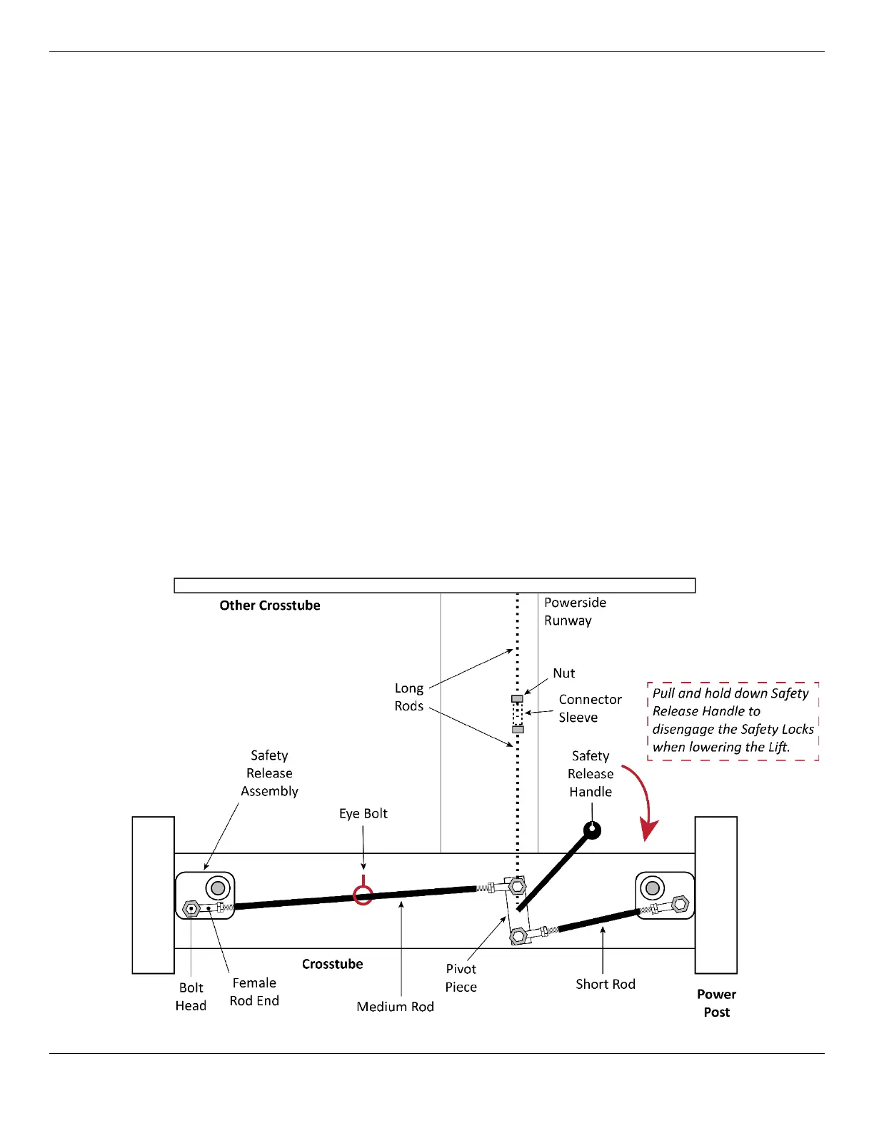
The Safety Lock Release Mechanism is made up of multiple pieces that connect at many locations:
• 2 Pivot Pieces. Pivot Piece attached to a Long Rod. One with the Handle attached, and one
with no Handle. Each Pivot Piece connects a Short Rod to a Medium Rod on the outside of each
Crosstube. PN varies based on model.
• 2 Short Rods (5755076). Connect the Safety Release Assemblies on each Crosstube to the
Pivot Pieces on the ends of the Powerside Post only.
• 2 Medium Rods (5755074). Connect to the other side of the Pivot Pieces and go to the Safety
Release Assembly.
• 8 Female Rod Ends (5505066). Make the connections to the Rods, four per each Crosstube.
• 8 Hex Head Bolts (5530011, 5530010). Used to secure the Female Rod Ends.
• 2 Safety Spacers (5755169). Go between the Pivot Piece and the Crosstube.
• 1 Connection Sleeve (5601318). Connects the two Long Rods to each other under the
Powerside Runway.
• 2 Eye Bolts (5530351). Hold the two Medium Rods in place along the outside of the Crosstube.
NOTICE The other Crosstube has the same Safety Lock Release Mechanism components, but
without a Handle. The Safety Release Handle
must
be installed next to the Power Unit.
The following graphic shows an overview of the Safety Lock Release system.