22
Locations 220 through 235 control the output options for the four auxiliary outputs. Each of the four outputs have four
individual programming locations that will be referred to in this section as DATA 1, DATA 2, DATA 3, and DATA 4. There
are 60 events or conditions that can be programmed to activate these four auxiliary outputs. The following descriptions of
these data locations will help you to understand how to program each of these locations. Refer to the worksheet for a full
list of individual locations.
DATA 1 (Partition)- The number programmed in the Data 1 location is used to direct the control as to which partition(s)
will be the source to initiate the trigger output on each of the four auxiliary outputs. When partitioning is not being used,
program a "0" in this location (factory default = "0"). When partitions are being used, programming selections are as
follows: "0" for all Partitions, "1" for Partition ONE, "2" for Partition TWO, and "3" for Partition THREE. Programming
selections for this location are "0" through "3".
DATA 2 (Duration)- The number programmed in the Data 2 location represents the amount of time that a trigger output
will remain activated. This duration time is selectable in 2 second increments, from 2 to 28 seconds. For example,
programming a "5" in the data 2 location will create a voltage trigger that would last for 10 seconds (2 x "5" = 10 seconds).
Programming a "0" will cause the output to follow the condition. Programming a "15" will latch the trigger output and a valid
user code must be entered to reset this condition. Programming selections for this location are the numbers "0" through
"15". NOTE: If you want to change the increments from seconds to minutes, follow the programming instructions for location
245 to do so, and the duration time will be selectable from 2 to 28 minutes.
DATA 3 (Category)- The number programmed in the Data 3 location will determine the category from which you will select
an activation event. Refer to the following event table to select which category number to program in this location.
Programming selections for this location are "0" through "15".
DATA 4 (Event)- The number programmed in the Data 4 location will determine the actual event in which you wish
to have the trigger activate upon. Refer to the event table to select which event number to program in this location.
Programming selections for this location are "0" through "15".
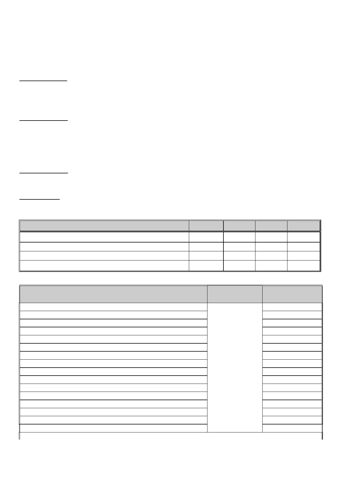
AUXILIARY OUTPUT DEFAULTS DATA 1 DATA 2
DATA 3 3
DATA 4 43
AUX OUTPUT #1 - ANY SIREN (Following) Locations 220-223 "0" "0" "1" "2"
AUX OUTPUT #2 - ANY SIREN (Latched) Locations 224-227 "0" "15" "1" "2"
AUX OUTPUT #3 - ARMED LED (Following) Locations 228-231 "0" "0" "1" "10"
AUX OUTPUT #4 - READY LED (Following) Locations 232-235 "0" "0" "1" "11"
DESCRIPTION OF EVENT DATA 3
CATEGORY
DATA 4
EVENT
Any "FIRE ALARM". “0"
Any "PANIC ALARM". “1"
Any "BURGLARY ALARM". “2"
Any "TROUBLE CONDITION". “3"
Any "BYPASS REPORT" “4"
Any "EARLY TO OPEN REPORT" “5"
Any "LATE TO CLOSE REPORT" “6"
"AC FAILURE" “7"
"DURESS" “8"
"AUXILIARY 1" [1] & [3] Double Keypress “9"
"AUXILIARY 2" [4] & [6] Double Keypress “10"
"CODE PAD PANIC" [¬] & [#] Double Keypress “11"
"CODE PAD TAMPER" “12"
"AUTOTEST" “13"
Any "FAILURE TO COMMUNICATE REPORT" “14"
"CANCEL"
“0"
“15"
Activation of "PRIORITY (FIRE) SIREN" “1" “0"
 Loading...