24
LOCATION 240-243: AUXILIARY OUTPUT CLOSING WINDOW
To enable the auxiliary output to activate on a pre-determined time a 24 hour (military) closing time must be programmed
into locations 240-243. For example, to enter a closing time of 6:30pm (18:30) program a "1" into location 240, an "8" in
location 241, a "3" in location 242 and a "0" in location 243. Also see aux output option - category 3 event 7 (open time aux
open time)
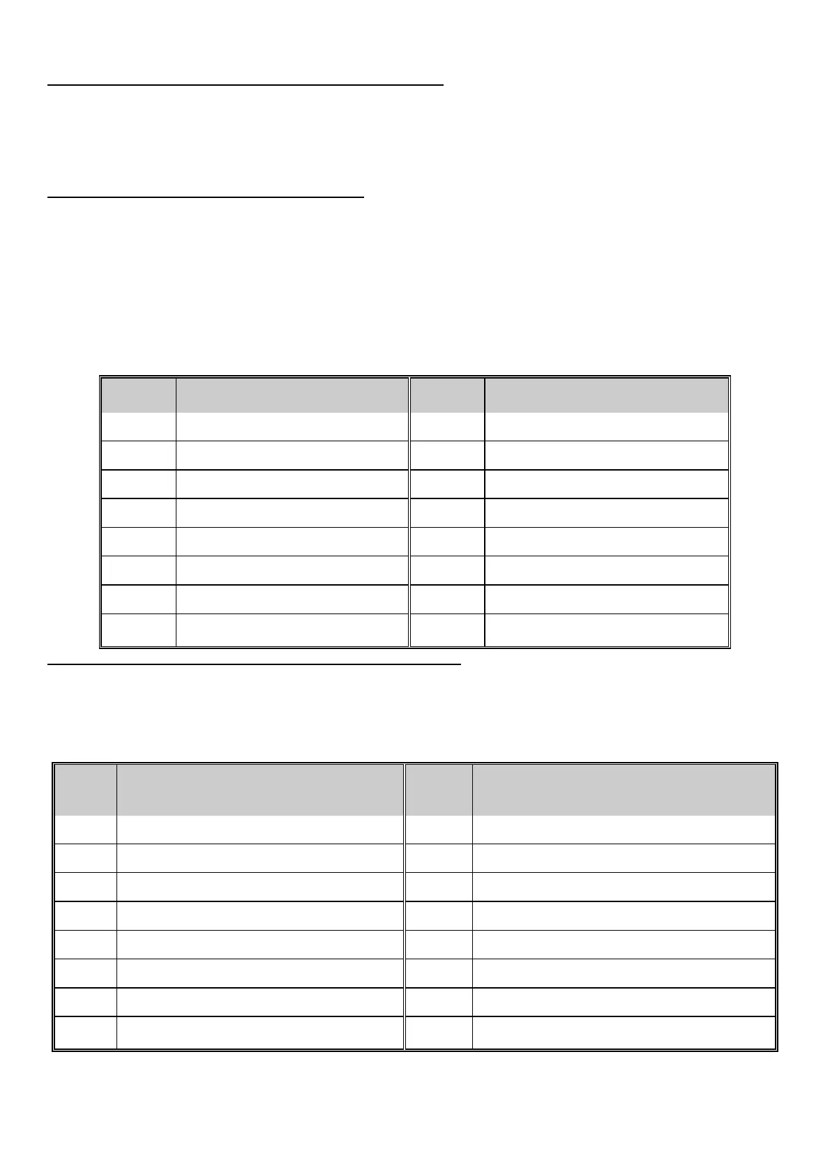
LOCATION 244: AUXILIARY OUTPUT INVERSION
The auxiliary outputs of the DL250 are normally POSITIVE (+) going NEGATIVE (-). They can be changed to a normally
NEGATIVE (-) going POSITIVE (+) by programming the appropriate number in this location. Auxiliary output 1 has a value
of "1", Auxiliary output 2 has a value of "2", Auxiliary output 3 has a value of "4", and Auxiliary output 4 has a value of "8".
The values for the outputs that you wish to change to NEGATIVE going POSITIVE must be added together and the total
programmed in this location. For example, if you wished to make outputs 2 (=2) and 3 (=4) NEGATIVE going POSITIVE,
you would program "6" (2+4=6) in this location. The output for pin 1 is automatically tied to the on board form A relay
(Terminal locations 20 & 21), and pin 2 is tied to the form C relay (Terminal location 22, 23 & 24). You should take this into
consideration when planning auxiliary output operation. If you need a relay output on pins 3 or 4 you must add a relay that
can be tripped with the voltage and current available at these pins. NOTE: THE PINS ARE CURRENT LIMITED TO 250
MICRO AMPS POSITIVE AND 20 mA NEGATIVE.
VALUE OUTPUT INVERSION VALUE OUTPUT INVERSION
0 NO AUX INVERTED 8 INVERT AUX 4 OUTPUT
1 INVERT AUX 1 OUTPUT 9 INVERT AUX 1 & 4 OUTPUT
2 INVERT AUX 2 OUTPUT 10 INVERT AUX 2 & 4 OUTPUT
3 INVERT AUX 1 & 2 OUTPUT 11 INVERT AUX 1, 2 & 4 OUTPUT
4 INVERT AUX 3 OUTPUT 12 INVERT AUX 3 & 4 OUTPUT
5 INVERT AUX 1 & 3 OUTPUT 13 INVERT AUX 1, 3 & 4 OUTPUT
6 INVERT AUX 2 & 3 OUTPUT 14 INVERT AUX 2, 3 & 4 OUTPUT
7 INVERT AUX 1, 2 & 3 OUTPUT 15 INVERT AUX 1, 2, 3 & 4 OUTPUT
LOCATION 245: AUXILIARY OUTPUT MINUTES TIMING ENABLE
The number programmed into this location will determine if the 4 auxiliary output(s) described in the above locations will
create 2 to 28 seconds, or 2 to 28 minutes voltage trigger outputs. If this location contains a "0" (factory default = "0"), the
output duration time is computed in seconds. By adding the value that corresponds to each pin number in the table below,
and programming the sum in this location, the "second" increments will convert to "minute" increments for the output(s)
selected:
VALU
E
CONVERTING OUTPUT TIMING VALUE CONVERTING OUTPUT TIMING
0 ALL AUXILIARIES ARE IN SECONDS 8 AUX 4 OUTPUT TIME TO MINUTES
1 AUX 1 OUTPUT TIME TO MINUTES 9 AUX 1&4 OUTPUT TIME TO MINUTES
2 AUX 2 OUTPUT TIME TO MINUTES 10 AUX 2&4 OUTPUT TIME TO MINUTES
3 AUX 1&2 OUTPUT TIME TO MINUTES 11 AUX 1,2&4 OUTPUT TIME TO MINUTES
4 AUX 3 OUTPUT TIME TO MINUTES 12 AUX 3&4 OUTPUT TIME TO MINUTES
5 AUX 1&3 OUTPUT TIME TO MINUTES 13 AUX 1,3&4 OUTPUT TIME TO MINUTES
6 AUX 2&3 OUTPUT TIME TO MINUTES 14 AUX 2,3&4 OUTPUT TIME TO MINUTES
7 AUX 1,2&3 OUTPUT TIME TO MINUTES 15 AUX 1,2,3&4 OUTPUT TIME TO MINUTES
 Loading...