28
channels are linked and a Step parameters is changed, e.g. High pass slope type, both channel values
will be forced to the same value.
parameters don't have discrete selections, instead they have a range of numerical values such
as gain, frequency or delay. These parameters can have offsets between them when the channels are
linked. If any linked parameter reaches the value limit, none of the linked parameters will be able to
move further in that direction.
Offset
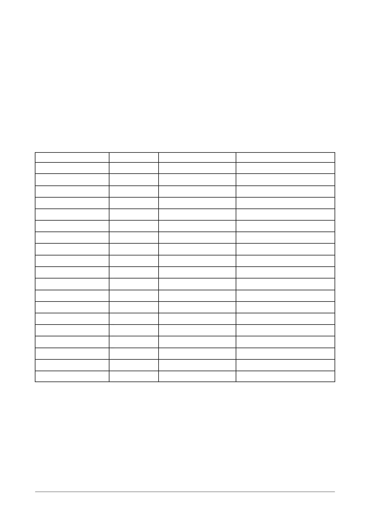
Table 1 Linked parameter relationships
Parameter Linking Type 2 Channel 3 Way LCR 2 Way
Input Delay Offset A-B A-B
Input EQ Type Step A-B A-B
Input EQ Frequency Offset A-B A-B
Input EQ +/- Offset A-B A-B
Output Name Offset 1-2, 3-4, 5-6 1-3, 4-6
Output Source Offset A(1, 3&5) / B(2, 4&6) A(1&4) / B(2&6) / A+B(3&5)
Output Gain Offset 1-2, 3-4, 5-6 1-3, 4-6
Output Limit Offset 1-2, 3-4, 5-6 1-3, 4-6
Output Delay Offset 1-3, 3-5, 2-4, 4-6 1-4, 2-5, 3-6
Output Delay Link Offset 1-3, 3-5, 2-4, 4-6 1-4, 2-5, 3-6
Output Polarity Step 1-2, 3-4, 5-6 1-3, 4-6
Output Lo Shape Step 1-2, 3-4, 5-6 1-3, 4-6
Output Lo Frequency Offset 1-2, 3-4, 5-6 1-3, 4-6
Output Hi Shape Step 1-2, 3-4, 5-6 1-3, 4-6
Output Hi Frequency Offset 1-2, 3-4, 5-6 1-3, 4-6
Output EQ Type Step 1-2, 3-4, 5-6 1-3, 4-6
Output EQ Frequency Offset 1-2, 3-4, 5-6 1-3, 4-6
Output EQ +/- Offset 1-2, 3-4, 5-6 1-3, 4-6
Output EQ Width Offset 1-2, 3-4, 5-6 1-3, 4-6
OPERATION
Manual del usuario/ User´s manual DSP-26