31 Vantec series User's Manual
Vantec Series | Amplifier
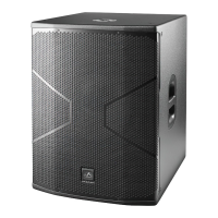
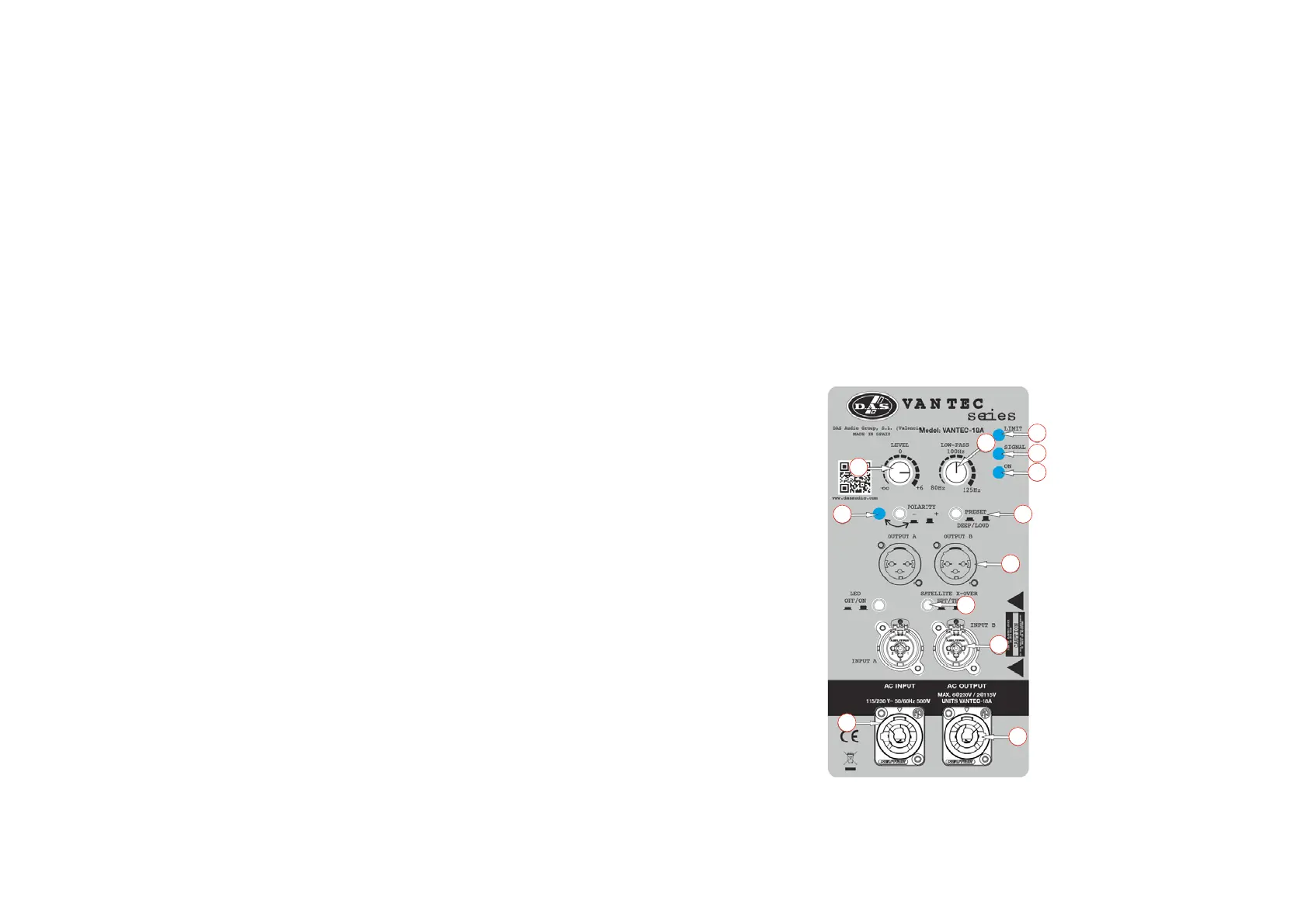
Description of VANTEC-18A
1. INPUT:
1/4” Jack+XLR combined socket-type input signal connectors. This is a balanced connector just
like the LOOP THRU connector with the following pin assignments:
1 or S =GND (ground).
2 or T =(+) Non inverted input.
3 or R =(-) Inverted input.
2. SATELLITE OUTPUT:
A and B, XLR-type output signal connectors for connecting several units together and sending
them all the same input signal or filtered signal (by using THRU/HPF).
3. LIMIT:
Red LED indicates amplifier saturation. Amplifier limiter indicator lights.
4. SIGNAL:
Green LED indicates signal presence.
5. ON:
Green LED indicates that the unit is ON.
6. SUB LEVEL:
Potentiometer for adjusting the unit level.
7. AC INPUT:
Standard PowerCon NAC3FCA mains connector (inserted, rotated and locked for ON). Only use
this equipment with an appropriate mains cord.
8. THRU/HPF:
‘SATELLITE OUTPUT’ selector to switch between full range signal or pass filter with cut-off
frequency of 100 Hz.
9. LOW-PASS CROSSOVER:
Button for adjusting the upper cut-off frequency for the subwoofer unit. We recommend a cut-
off frequency of 100 Hz for vantec series use.
10. PHASE:
Switch for inverting the phase of the unit.
11. PRESET DEEP/LOUD:
Button for switching between two types of frequency response, DEEP or LOUD.
10. AC OUTPUT:
PowerCon NAC3FCB connector for AC loop thru allows up to 8 units when using a 230V version
(see unit’s label)). Only use this equipment with an appropriate mains cord.
1
2
3
4
5
6
7
8
9
10 11
12