23 Vantec series User's Manual
Vantec Series | Amplifier
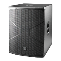
Description: VANTEC-12A / 15A / 215A
1. MASTER VOLUMEN AND DSP CONTROL:
Use the encoder to select the desired output volume and push/hold it to access to the different DSP and cabinet
settings.
2. MAIN SCREEN:
In the main screen all selected parameters and settings are shown. Besides this, there are two input level
indicators on the left , one output level indicator on the right and the center area is reserved to display messages
as Input Clip or Limit.
3. INPUT CONNECTORS:
1/4” Jack+XLR combined socket-type input signal connectors. This is a balanced connector just like the LOOP
THRU connector with the following pin assignments:
1 or S =GND (ground).
2 or T =(+) Non inverted input.
3 or R =(-) Inverted input.
4. OUTPUT:
XLR-type output signal connector for connecting several units together and sending them all the same signal.
The user can select the signal going out; can be Ch1, Ch2 or MIX (see 6).
5. INPUT GAIN CONTROL:
For channels 1, 2 and AUX IN, gain control, line and microphone.
Note: Wireless Audio Signal is controlled with gain knob 1.
6. OUTPUT MIXSELECTOR:
It allows the user to select which input channel signal to be sent to other cabinets. User can select Ch1, Ch2 or
both (Mix).
7. AUX IN:
3.5 mm audio jack input for connecting external audio media devices, such as MP3 players. The input source is
controlled with Gain control 1.
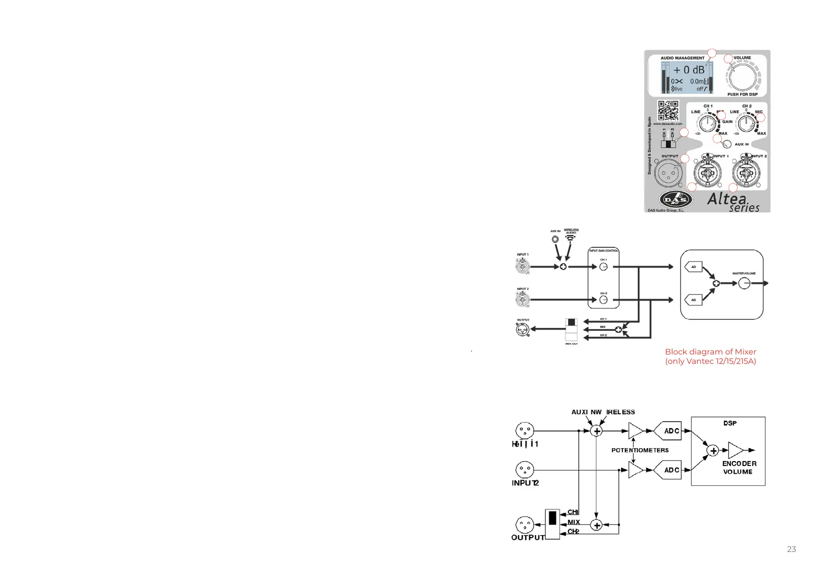
Block diagram of Mixer
(only Vantec 12/15/215A)
Block diagram of Mixer
(only Vantec 12/15/215A with
Firmware v2.X)
VANTEC-12A / 15A / 215A
1
2
6
5
5
7
4
3
3