20
5.0 CHARGING
5.1 Voltage Phase Check
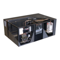
5.1.1 Evaporator
Prior to charging, the correct voltage phasing should be checked on the indoor evaporator. Check
blower direction on the evaporator by momentarily energizing the fan motor. Reverse any two of the
three line voltage wires at the line voltage fi eld connection point to change the blower rotation.
Although the scroll compressor is phase dependent, units shipped from the factory are run tested,
ensuring the compressor rotation is consistent with the evaporator fan motor. However, a fi eld change-
out of the compressor may require checking proper phase. An out-of-phase compressor will draw
relatively low amps and both suction and discharge pressures will remain nearly equal.
5.1.2 Secondary Heat Exchanger
The secondary heat exchanger may be ordered as three phase but the individual fan motors are single
phase and will only run in one direction. Check operation by placing a momentary jumper across
low voltage fi eld terminals #39 and #40. (Disconnect pumps on glycol systems unless already fi lled
with water/glycol solution.) This will energize the control circuit. Fans may not run because: 1) the
thermostat setpoint is above the current ambient, or 2) the #1 fan on air cooled condensers with fan
speed control react to head pressure. The fan will not run until the head pressure is well over 200
psi.
5.2 Air Cooled Systems
5.2.1 Split Indoor Air Cooled Systems Charging
After the fi eld refrigerant piping is properly completed, connect the refrigerant drum to the low side
and charge with vapor. Charge with approximately three lbs. per nominal ton.
For example, a model DALA 0834-COS is a nominal 8 ton single circuit unit. Charge with about 24
lbs. of refrigerant to begin. It is likely that more refrigerant will be required to complete the charging
procedure. Make sure all hoses are properly purged. Review the model number carefully because
LCS units are available with either single or dual compressors.
Before starting a compressor, the crankcase heater should be energized for a minimum
of 12 hours to reduce the possibility of liquid slugging on start-up. Failure to energize
the crankcase heater could result in compressor damage.
Start the evaporator fan and compressor. Check the liquid line sight glass to get a feel for the
approximate charge. Bubbles in the sight glass are not unusual at this point and can be caused by
fl ashing from liquid line pressure drop, low sub-cooling or low charge. It is likely that more refrigerant
will be required to complete the charging procedure.
Adjust the refrigerant charge until the sight glass clears or has only sparse bubbles. The unit should
be allowed to stabilize for several minutes before meaningful measurements can be taken.
A properly charged system operating at typical parameters will have a head pressure of 240 - 295
psi for R 407C and 340 - 415 psi for R 410A. Suction temperature should be 58 psi or greater for R