USB-KBD DEFAULT SETTINGS
USA keyboard, FIFO enabled, inter-character and inter-code delays disabled,
control character emulation = ctrl+shift+key.
DATA FORMAT
: code identifier disabled, no field adjustment, code length not
transmitted, no header, terminator = ENTER, character replacement disabled.
RS232 Standard DEFAULT SETTINGS
9600 baud, no parity, 8 data bits, 1 stop bit, no handshaking, delay disabled, rx
timeout 5 sec., ack/nack disabled, FIFO enabled, serial trigger lock disabled.
DATA FORMAT
: code identifier disabled, no field adjustment, code length not
transmitted, no header, terminator = CR-LF, character replacement disabled.
WEDGE DEFAULT SETTINGS
USA keyboard, caps lock off, caps lock auto-recognition enabled, num lock
unchanged, inter-character and inter-code delays disabled, control character
emulation = ctrl+shift+key.
DATA FORMAT
: code identifier disabled, no field adjustment, code length not
transmitted, no header, terminator = ENTER, character replacement disable.
PEN DEFAULT SETTINGS
interpret mode, conversion to code 39 disabled, output level normal, idle level
normal, minimum output pulse 600 µs, overflow medium, inter-block delay disabled.
CODE SELECTION
EAN 8/EAN 13 / UPC A/UPC E without ADD ON
check digit transmitted, no conversions
Interleaved 2/5
check digit control and transmission, variable length code; 4-99 characters
Standard Code 39
no check digit control, variable length code; 1-99 characters
Code 128
variable length code; 1-99 characters
EAN 128, ISBT128, Code 93, Codabar, pharmaceutical codes, MSI,
Plessey, Telepen, Delta IBM, Code 11, Code 16K, Code 49, RSS Codes
Heron
D130
Electrical Features
Power Supply
RS-232 interface
Maximum
Operating
180 mA @ 5 Vdc
155 mA @ 5 Vdc
Reading Indicators LED, Good Read Spot, Beeper
Optical Features
Sensor CCD solid state (2048 pixels)
Illuminator LED array
Wavelength 630 ~ 670 nm
Max. LED Output Power 0.31 mW
LED Safety Class Class 1 EN 60825-1
Reading Field 2 ~ 27 cm (20 mils)
PCS (Datalogic Test Chart)
Environmental Features
°
°
Storage Temperature -20 °C to + 70 °C (-4° to +158 °F)
Humidity 90% non condensing
Drop Resistance
IEC 68-2-32 Test ED
1.8 m (5.9 ft)
ESD Protection 16 KV
Mechanical Features
Cable Length 2 m (6 ft 6 in)
RESTORE DEFAULT
Ì$+$*oÎ
To change the defaults refer to the
HHD II Software Configuration Manual,
or to the
Datalogic Aladdin
Configuration program, both downloadable from the website.
Select one of the interface codes according to your application.
USB INTERFACE SELECTION
When configuring USB-
COM, the relevant files and drivers must be installed from
the USB Device Installation software, which can be downloaded from the web
site http://www.datalogic.com.
PEN EMULATION INTERFACE SELECTION
RS-232 INTERFACE SELECTION
WEDGE INTERFACE SELECTION
Many other interfaces are supported and can be selected from the HHD II Software
Configuration Manual
available online at datalogic.com. Other supported interfaces:
: USB-IBM-Table Top; USB-KBD-APPLE
WEDGE: IBM XT; IBM SURE1; IBM Terminal 3153; IBM Terminals 31xx, 32xx,
34xx, 37xx
;
VT220 style Keyboards; Digital Terminal VT2xx/VT3xx/VT4xx; APPLE
ADB Bu
s
-KBD and Wedge users should select one of the following wedge keyboard
nationality codes according to your keyboard.
DATA FORMAT TERMINATORS
For your convenience, some common Terminators are given below. For other
Header/Terminator selections, Data Format and Advanced Data Format
parameters, see the
HHD II Software Configuration Manual.
Enter
Tab
None
Read the TEST code below.
Code 128
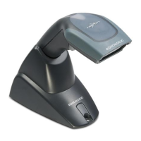
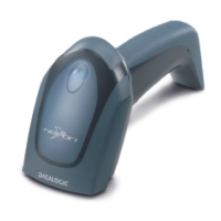
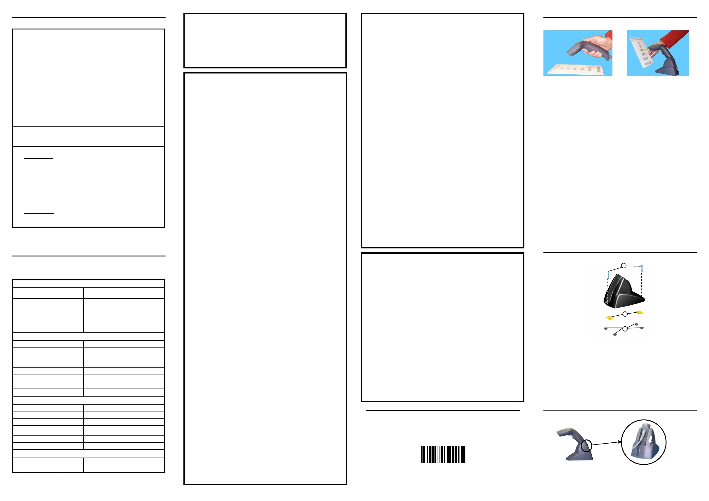
SERIES READERS
readers automatically scan barcodes at a distance
. Simply aim and pull
the trigger. Code scanning is performed along the center of the light bar emitted
from the reading window. This bar must cover the entire code.
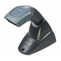
Successful scanning is obtained by tilting the scanner with respect to the barcode
to avoid direct reflections, which impair the reading performance
(s
).
Successful reading is signaled
by an audible tone plus a good-read green spot.
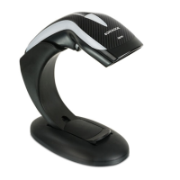
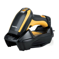
reader is correctly inserted
into the stand, it is immediately ready to
automatically read any code present in its reading area without pressing
the trigger.
Furthermore, a green aiming light is continuously emitted to facilitate the
positioning of the barcode to be read
(see the figure above).
To guarantee single code reading, same code consecutive reading requires the
code to be removed from the reading area (no decoding) before the reader will
accept the same code.
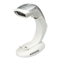
The stand can be mounted by using self
-
tapping screws, double sided adhesive
strips or rubber feet:
Mount the stand directly to the surface using the self-tapping screws;
Carefully
clean the bottom surface of the stand and the table surface.
Remove the protective plastic from one side of the adhesive strips and stick
them on the stand bottom. Then, remove the plas
tic from the other side of the
strips and affix the stand to the table;
Carefully
clean the bottom surface of the stand, remove the protective film
from the rubber feet and stick them in the corresponding housing on the
bottom surface. It is also possible to affix an optional metal plate.
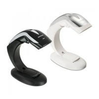
Pair the reader to the stand
, taking care
to insert the handle into the stand clip (see
figure above). Correct insertion will be signaled by a beep; then, the reader will be
ready to read barcodes.
 Loading...