V110120E iBoot-G2+ Page 6
4.3. Expansion Connections
iBoot-G2+ has two Expansion Ports, Exp1 and Exp2 for connection to iBoot-Exp, or for use as General
Purpose Inputs and Outputs (GPIO). Mode settings on the iBoot-G2+ determine how the expansion ports
function.
Connections to the iBoot-Exp are made using screw terminal blocks. The screw terminal blocks are on
removable connectors for easy cable fabrication.
Make sure screw terminals are tightened securely and that there are no loose strands of cable, or excessive
stripped wires.
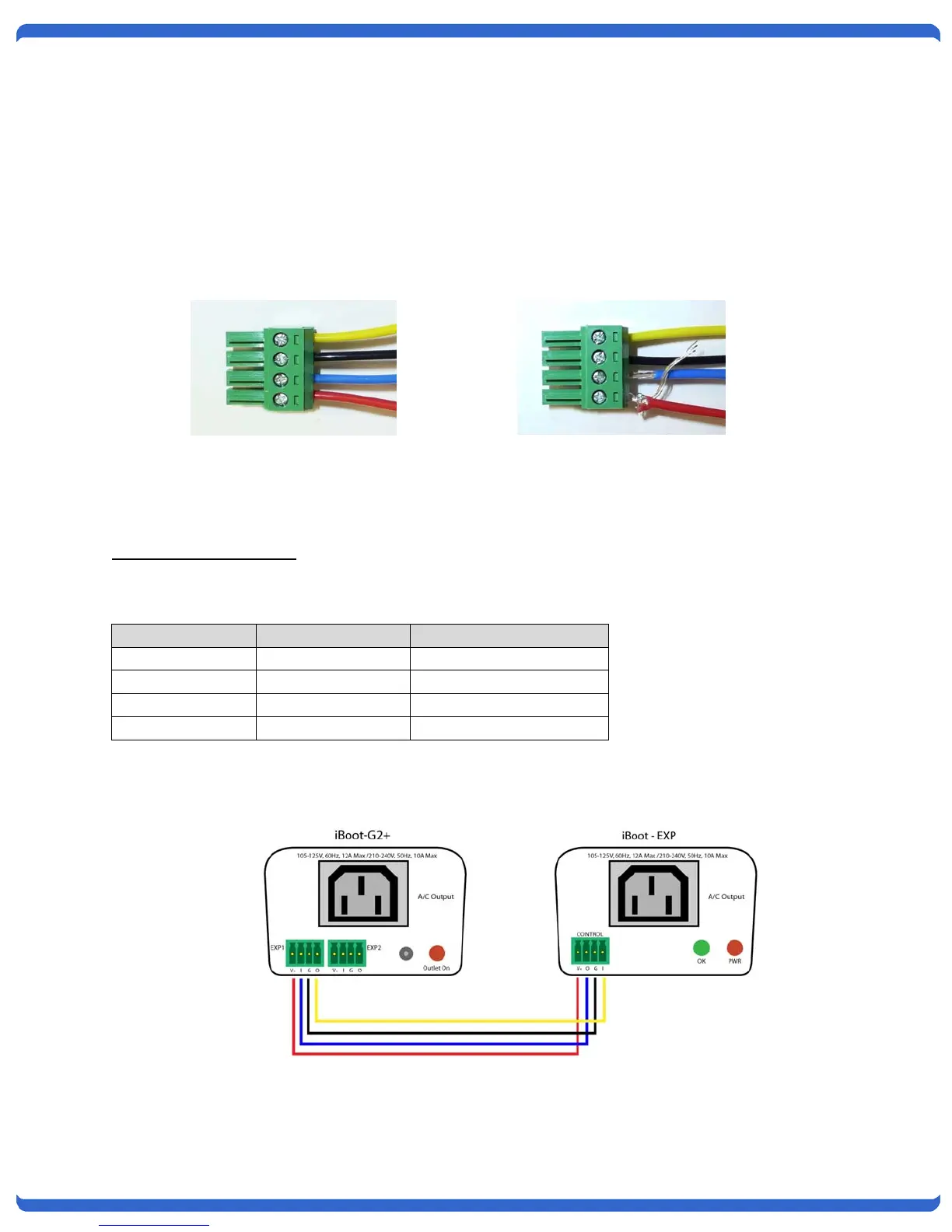
Connecting to iBoot-Exp
Terminal blocks are connected pin-to-pin with the iBoot-Exp as shown:
Connect:
Function iBoot-G2+ iBoot-Exp
Power V+ Power Out V+ Power In
Feedback I Input O Output
Ground G Ground G Ground
Command O Output I Input
Expansion units (iBoot-Exp) are shipped with a cable for easy connection to the iBoot-G2+ . Maximum cable
length is 1000 ft (305 m) using 22 AWG wire.
iBoot
G2+ to iBoot
EXP Connections
Poor Screw Terminal
Connections.
Note Loose Wires and
Excessive Stripping
Proper Screw Terminal
Connections