V110120E iBoot-G2+ Page 7
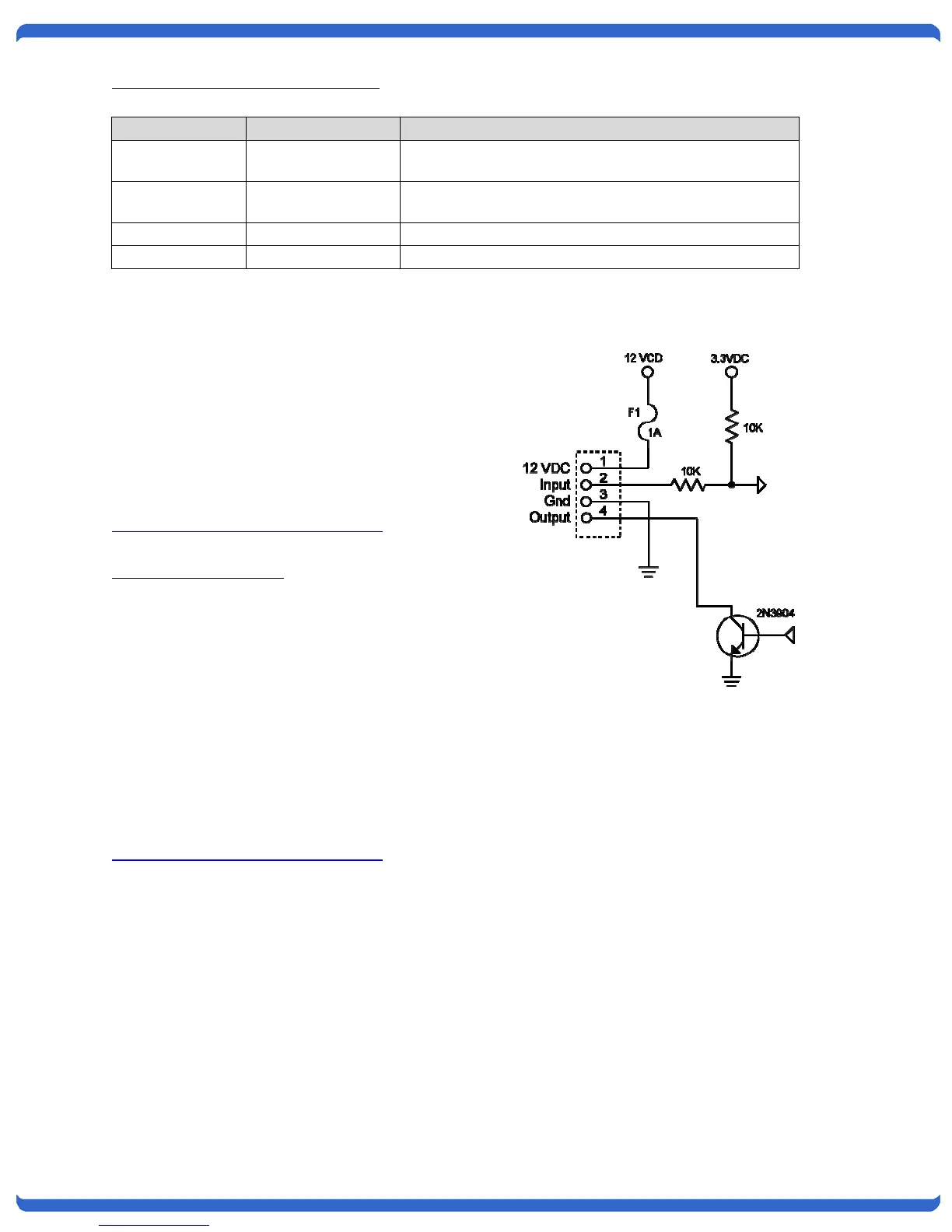
Connection to General Purpose I/O
Function iBoot-G2+ Description
Power V+ Power Out This is +12 VDC power out from the iBoot-G2+
Maximum current 100 mA
Feedback I Input Input for status signals. Dry Contact input or Open
Collector.
Ground G Ground Signal Ground for Input and Output
Command O Output 2N3904 NPN Transistor. 100 mA Maximum
4.4. USB Connection
The iBoot-G2+ has a USB connection that can be
used for:
• Connection to a PC for setup and control
• Connection to a PC for heartbeat monitoring
To use the USB port, install the USB driver.
Download the driver at
http://dataprobe.com/support/iboot.html
USB Driver Installation
• Run ibootG2Driver.exe prior to connecting the
iBoot-G2+ to the USB port of the PC.
• Connect the USB iBoot-G2+ to a USB port of
the PC.
• The PC will discover the iBoot-G2+ and assign a
COM port. To find the COM port go to
• Control Panel > System > Device Manager >
Ports (COM & LPT) The com port assigned will
be USB Serial Port (COMn)
The USB port can now be used with a standard
Terminal Client (like HyperTerminal) to communicate
directly with the iBoot-G2+. Dataprobe also provides
a simple terminal program (EZ Term) at
http://dataprobe.com/support/iboot.html
Schematic of Input and Output Connections
Used as General Purpose I/O