EN Dateq BCS70 Manual BCS71(GE) dual mono input module 8
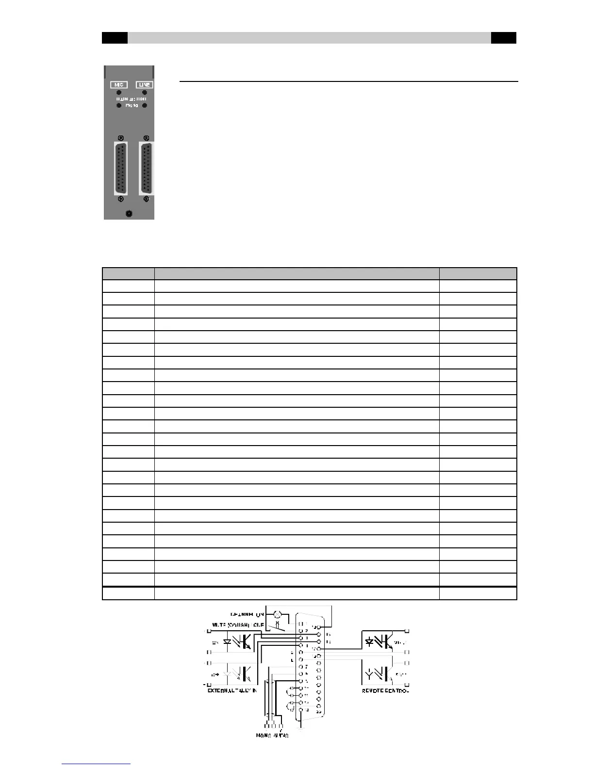
BCS71(GE) connector board
GAIN ADJUST The input-level can be trimmed separately for both
the microphone and line input. Use a small
screw driver to adjust the trimmers in the holes
marked ‘mono’.
MIC Mono microphone input on 25-pin female Sub-D
connector.
LINE Electronically balanced mono line input on 25-pin
female Sub-D connector.
BCS71(GE) Audio and Control Input / Output (Sub-D 25-pin female)
Pin Function Type
1 Channel ON / External CUE lamp Out
14 External CUE lamp / External CUE or Cough switch D-GND
2 External CUE or Cough switch In
15 External tally ON - (opto-coupler cathode) In
3 External tally ON + (opto-coupler anode) In
16 External tally OFF - (opto-coupler cathode) In
4 External tally OFF + (opto-coupler anode) In
17 Remote control Start (opto-coupler collector) Out
5 Remote control Start (opto-coupler emitter) Out
18 Remote control Stop (opto-coupler collector) Out
6 Remote control Stop (opto-coupler emitter) Out
19 -
7 Audio Mono + In
20 -
8 Audio Mono - In
21 -
9 Audio GND A-GND
22 -
10 Insert Send + (no insert used: connect to pin 11) Out
23 -
11 Insert Return + (no insert used: connect to pin 10) In
24 -
12 Insert Return - (no insert used: connect to pin 25) In
25 Insert GND (no insert used: connect to pin 12) Out
13 Frame GND FRAME