Do you have a question about the Datex-Ohmeda 7100 and is the answer not in the manual?
Details the scope of service information for the 7100 ventilator.
Outlines procedures for using service manuals and performing tests.
Explains warnings, cautions, and various symbols found in the manual.
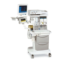
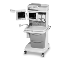
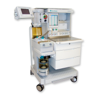
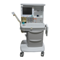
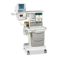
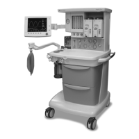
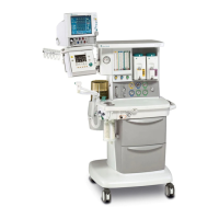
Provides an overview of the 7100 ventilator and its role in anesthesia machines.
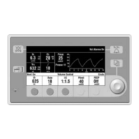
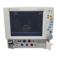
Lists key features, sensors, and operational modes of the 7100 ventilator.
Details the safety features including overpressure protection and electrical limits.
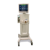
Identifies and describes the major components of the 7100 ventilator.
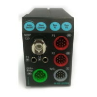
Details the electronic and electrical subassemblies and modules of the ventilator.
Describes the mechanical components and subsystems of the ventilator.
Lists required service mode calibrations and system checkout procedures.
Explains the ventilator's self-test routines performed at powerup, continuously, and periodically.
Describes how to enter and navigate the Service Mode for testing and calibration.
Menu to identify current software version, date, hardware ID, and system on-time.
Displays recent alarm messages, including bootup count, time, and number of occurrences.
Lists recent error messages with details on bootup count, time, error message, and address.
Allows setting the display language for normal operation of the ventilator.
Menu for adjusting parameters to personal preference or compensating for influences.
Settings tailored to the specific machine, including altitude and drive gas.
Service level calibrations for components to maintain specified accuracy.
Tests to check individual subsystems of the ventilator.
Option to upgrade ventilator features by entering a purchased key code.
Directs users to relevant sections for ventilator problems and error messages.
A table correlating symptoms with probable causes and recommended actions.
Lists recent alarm and error messages, their causes, and service repair actions.
Visual diagnostic guides for various ventilation issues.
Step-by-step guide for installing ventilator software using a memory stick.
Procedures for accessing and replacing components within the control module.
Instructions for removing and servicing the pneumatic engine and its components.
Procedure for replacing the MIA in Aestiva machines.
Instructions for accessing and replacing the SAB and power cord/harness.
Provides guidance on lubrication, screw locking, and fitting installation.
Lists essential tools required for service procedures, including part numbers.
Index of figures and their corresponding page numbers for ventilator components.
Block diagram illustrating the Aestiva 7100 ventilator system components.
Block diagram illustrating the Aespire 7100 ventilator system components.
Pneumatic diagram for the Aestiva 7100 anesthesia machine.
Pneumatic diagram for the Aespire 7100 anesthesia machine.
Wiring diagram for the Aestiva 7100 ventilator.
Diagram showing the Aestiva 7100 pneumatic engine and its board.
Diagram of Aestiva 7100 breathing system switches connecting to MIA.
Wiring diagram for the Aespire 7100 ventilator.
Tubing diagram for the Aespire 7100 ventilator.
Block diagram detailing the components of the control module.
Block diagram illustrating the display panel components.
Details the scope of service information for the 7100 ventilator.
Outlines procedures for using service manuals and performing tests.
Explains warnings, cautions, and various symbols found in the manual.
Provides an overview of the 7100 ventilator and its role in anesthesia machines.
Lists key features, sensors, and operational modes of the 7100 ventilator.
Details the safety features including overpressure protection and electrical limits.
Identifies and describes the major components of the 7100 ventilator.
Details the electronic and electrical subassemblies and modules of the ventilator.
Describes the mechanical components and subsystems of the ventilator.
Refers to the planned maintenance schedule in the respective machine manual.
Procedures for servicing the free breathing valve, including flapper replacement.
Describes the test setup and procedure for the Mechanical Overpressure Valve.
Step-by-step guide for installing ventilator software using a memory stick.
Procedures for accessing and replacing components within the control module.
Instructions for removing and servicing the pneumatic engine and its components.
Procedure for replacing the MIA in Aestiva machines.
Instructions for accessing and replacing the SAB and power cord/harness.
Provides guidance on lubrication, screw locking, and fitting installation.
Lists essential tools required for service procedures, including part numbers.
Index of figures and their corresponding page numbers for ventilator components.
Block diagram illustrating the Aestiva 7100 ventilator system components.
Block diagram illustrating the Aespire 7100 ventilator system components.
Pneumatic diagram for the Aestiva 7100 anesthesia machine.
Pneumatic diagram for the Aespire 7100 anesthesia machine.
Wiring diagram for the Aestiva 7100 ventilator.
Diagram showing the Aestiva 7100 pneumatic engine and its board.
Diagram of Aestiva 7100 breathing system switches connecting to MIA.
Wiring diagram for the Aespire 7100 ventilator.
Tubing diagram for the Aespire 7100 ventilator.
Block diagram detailing the components of the control module.
Block diagram illustrating the display panel components.
| Manufacturer | Datex-Ohmeda |
|---|---|
| Model | 7100 |
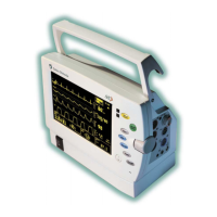
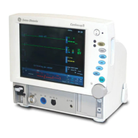
| Display | Color LCD |
| ECG | Optional |
| SpO2 | Optional |
| NIBP | Optional |
| Invasive Blood Pressure | Optional |
| Temperature | Optional |
| Agent Identification | Optional |
| Recorder | Optional |
| Alarms | Yes, adjustable limits |
| Power Supply | AC Mains, Battery Backup |
| Weight | 33 lbs (15 kg) |