4: Technical Description
4-2 PRC-BC4-MS
4.2 Charging Circuit
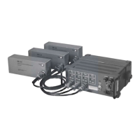
The PRC-BC4 consists of four charging circuits with the three charging
stations interfaced through the front panel and the fourth through the power
connector on the back. Since all four charging circuits are identical, the
following technical description only references charging circuit BATT 1.
The PRC-BC4 charges BB-LA6s in three charging state levels:
• Bulk charge
• Overcharge
• Float charge
4.2.1 Bulk Charge State
Each charging stations includes charger IC U1, that detects voltage and
controls the charge levels. When an operator connects a BB-LA6 to the charge
station, U1 detects voltage on the output line and initiates the bulk charge
state. U1 also samples voltage through divider resistors R2 and R5 at the
sampling input pin 12. Pin 7, normally at ground, provides the lower reference
for the divider. When power is removed, pin 7 floats so that no current can
flow out of the battery when the power is turned off.
The bulk charge begins when the voltage on pin 12 exceeds 2.5 VDC, which
corresponds to 5.0 VDC from the battery. If the battery voltage is lower than
5V, the charger remains in fault condition and no current flows to the battery.
This protects the PRC-BC4 from BB-LA6s with shorted cells.
Series pass transistor Q1 controls the charge current to the BB-LA6. In the
bulk charge state, charger IC U1 drives Q1 through pin 16. Resistor R4, in
series with the Q1 emitter, provides current-limiting and current-sensing that
allows U1 to maintain the charge current at 1.1A. Capacitor C1 provides
filtering for internal driver Q1. Diode D1 prevents the BB-LA6 from
discharging when the PRC-BC4 is turned off.
The bulk charge state continues until the BB-LA6 voltage reaches the preset
level (14.0 VDC) determined by the ratio of resistors R1, R3 and R6 sampled
at pin 13. When the battery voltage reaches 14.0 VDC, the charging circuit
goes into the overcharge state.
4.2.2 Overcharge State
The overcharge state maintains the battery voltage at 14.0 VDC until the
current decreases by 10% of the bulk charge current (110 mA). This state
brings the BB-LA6 back to full capacity without damaging the cells.
Charger IC pin 1, the charge state output, toggles when the charge current
drops by 10% of the bulk charge current. The overcharge terminate pin (pin 8)
connects to pin 1. When pin 1 toggles, it forces the charger into float state.