5: Maintenance
5-2 PRC-BC4-MS
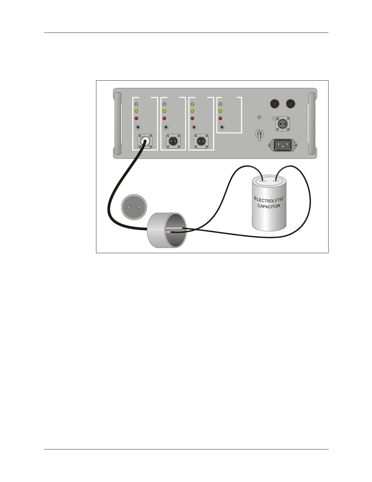
4. The READY LED for charging station BATT 1 should light up in a few
seconds. If it does not, measure the capacitor voltage to make sure it is
greater than 6 VDC. If the capacitor voltage is above 6 VDC, the
charger circuit has a fault.
DC Current
Check
1. Connect the DC ammeter, 6.8 ohm and 2.2 ohm resistors in series and
connect them across the capacitor (refer to Figure 5-2 on page 5-3).
2. Measure the DC current. It should be 1.1A ±0.1A. The CHARGING
LED for charging station
BATT 1 should be lit when the ammeter and
resistors are connected.
3. Disconnect the ammeter and resistors. The READY LED should light
up after a few seconds.
Figure 5-1 Charger Output Check Setup
BATT. 1
CHARGING
READY
FAULT
RESET
BATT. 2
CHARGING
READY
FAULT
RESET
BATT. 3
CHARGING
READY
FAULT
RESET
INTERNAL
CHARGING
READY
FAULT
RESET