5: Maintenance
PRC-BC4-MS 5-5
5.2.2 Troubleshooting Procedure
The following troubleshooting procedure provides specific steps to isolate
faults. Since all four charging circuits are identical, for steps that deal with the
charging circuit, this procedure references components in the first charging
station (BATT 1).
Note: The term IC refers to the UC309N charger IC, and the term op amp
refers to the LM324 operational amplifier.
Current Source
This section assumes a failure occurred during the “DC Input Circuitry
Check” procedure on page 5-4 if the READY LED does not light up.
1. Measure the DC voltage at the rectifier bridge BR1 (+) terminal. It
should be 20 ±3.0 VDC for AC operation; if not, refer to “AC Power
Supply” on page 5-7.
For DC operation the DC voltage at the rectifier bridge should be
about 1 VDC less than the DC supply voltage; if not, refer to “Reverse
Current Protection” on page 5-4.
2. Observe the front panel status LEDs. If none of them are lit, refer to
“Status LEDs” on page 5-8.
3. If the
CHARGING LED is lit, skip to step 7.
4. With more than 6 VDC across the capacitor, the FAULT LED should
now be lit. On the IC, measure the DC voltage at pin 7. If it is more
than 100 mV, replace the IC.
5. On the IC, measure the DC voltage at pin 12. If it is less than 3 VDC,
check the resistive divider (R5, R2) at pin 12.
6. On the IC, check for a short circuit at pin 11 (pin 11 should be high).
This output pin drives the
FAULT LED through a series resistor on the
Display board. If the FAULT LED is not lit, replace the IC.
7. The
CHARGING LED should now be lit. If more than one LED is lit,
refer to “Status LEDs” on page 5-8.
8. On pass transistor MJE2955, measure the voltage from the emitter to
the base. If it is between 0.6 to 1.0 VDC, skip to step 9.
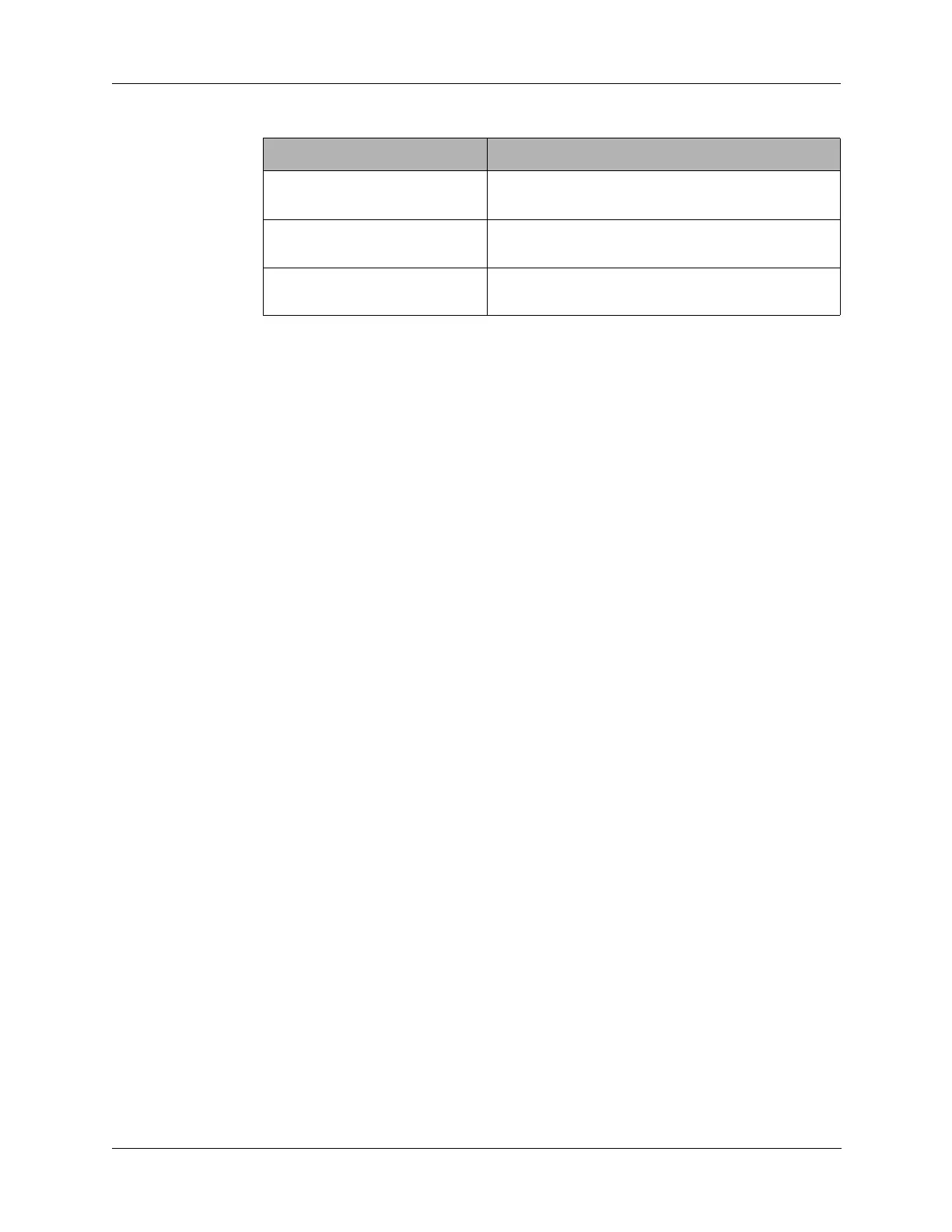
“Undervoltage Protection
Circuit Check” on page 5-3
Refer to “Undervoltage Protection” on page 5-7.
“Reverse Current Protection”
on page 5-4
Refer to “Reverse Current Protection” on page
5-7.
“DC Input Circuitry Check” on
page 5-4
Refer to “Reverse Current Protection” on page
5-7.
Table 5-1 Troubleshooting Index
Failed Test Section Troubleshooting Section