EasyManua.ls Logo

Datsun 1000 - Page 70

Datsun 1000
224 pages
Print Icon
To Next Page IconTo Next Page
To Previous Page IconTo Previous Page
Loading...
14
MaJlUal
Transmission
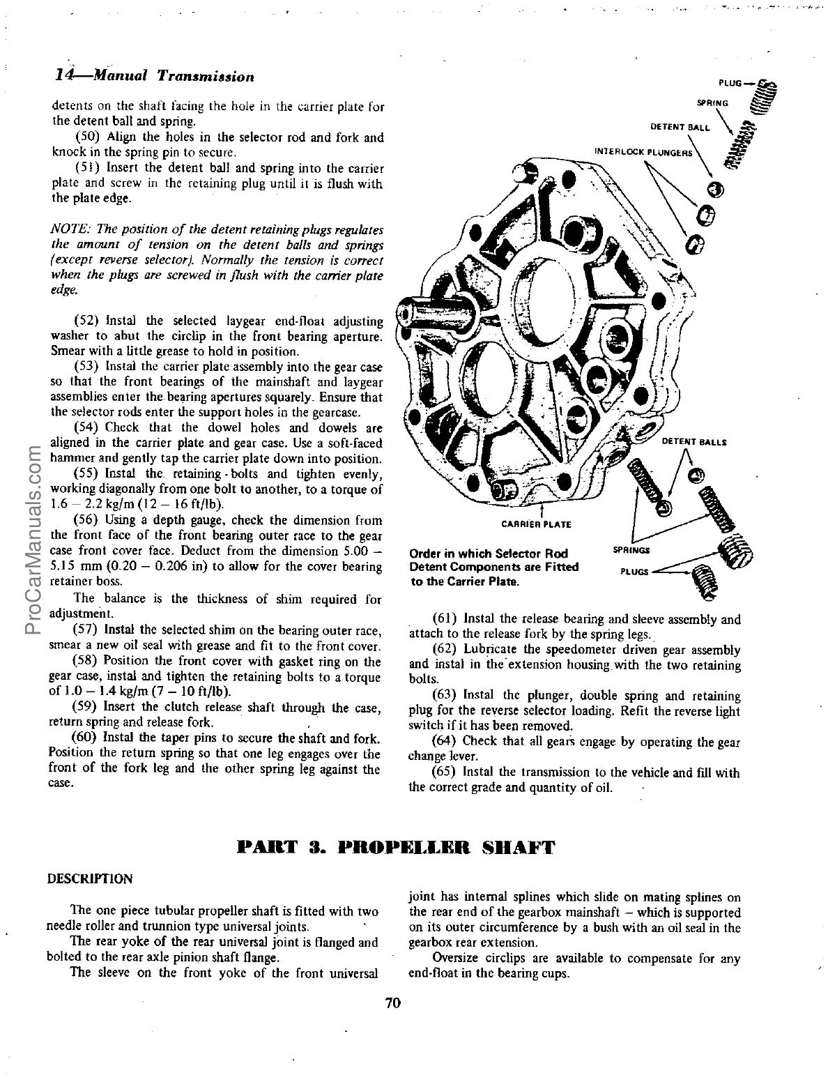
detents
on
the
shaft
facing
the
hole
in
the
carrier
plate
for
the
detent
ball
and
spring
50
Align
the
holes
in
the
selector
rod
and
fork
and
knock
in
the
spring
pin
to
secure
51
Insert
the
detent
ball
and
spring
into
the
carrier
plate
and
screw
in
the
retaining
plug
until
it
is
flush
with
the
plate
edge
NOTE
The
position
of
the
detent
retaining
plugs
regulates
the
amount
of
rension
on
the
detent
balls
and
springs
except
reverse
selector
Normally
the
tension
is
correct
when
the
plugs
are
screwed
in
flush
with the
carrier
plate
edge
52
Instal
the
selected
laygear
end
float
adjusting
washer
to
abut
the
circlip
in
the
front
bearing
aperture
Smear
with
a
little
grease
to
hold
in
position
53
Instal
the
carrier
plate
assembly
into
the
gear
case
so
that
the
front
bearings
of
the
mainshaft
and
laygear
assemblies
enter
the
bearing
apertures
squarely
Ensure
that
the
selector
rods
enter
the
support
holes
in
the
gearcase
54
Check
that
the
dowel
holes
and
dowels
are
aligned
in the
carrier
plate
and
gear
case
Use
a
soft
faced
hammer
and
gently
tap
the
carrier
plate
down
into
position
55
Instal
the
retaining
bolts
and
tighten
evenly
working
diagonally
from
one
bolt
to
another
to
a
torque
of
1
6 2
2
kg
m
12
16
ft
lb
56
Using
a
depth
gauge
check
the
dimension
from
the
front
face
of
the
front
bearing
outer
race
to
the
gear
case
front
cover
face
Deduct
from
the
dimension
5
00
5
15
mm
0
20
0
206
in
to
allow
for the
cover
bearing
retainer
boss
The
balance
is
the
thickness
of
shim
required
for
adjustment
57
Instal
the
selected
shim
on
the
bearing
outer
race
smear
a
new
oil
seal
with
grease
and
fit
to
the
front
cover
58
Position the
front
cover
with
gasket
ring
on
the
gear
case
instal
and
tighten
the
retaining
bolts
to
a
torque
of
1
0 14
kg
m
7 10
ft
lb
59
Insert
the
clutch
release
shaft
through
the
case
return
spring
and
release
fork
60
Instal
the
taper
pins
to
secure
the
shaft
and
fork
Position
the
return
spring
so
that
one
leg
engages
over
the
front
of
the
fork
leg
and
the
other
spring
leg
against
the
case
61
Instal
the
release
bearing
and
sleeve
assembly
and
attach
to
the
release
fork
by
the
spring
legs
62
Lubricate
the
speedometer
driven
gear
assembly
and
instal
in
the
extension
housing
with
the
two
retaining
bolts
63
Instal
the
plunger
double
spring
and
retaining
plug
for the
reverse
selector
loading
Refit
the
reverse
light
switch
if
it
has
been
removed
64
Check
that
aU
geari
engage
by
operating
the
gear
change
lever
65
Instal
the
transmission
to
the
vehicle
and
fIll
with
the
correct
grade
and
quantity
of
oil
PART
3
PROPELLER
SHAFT
DESCRIPTION
The
one
piece
tubular
propeller
shaft
is
fItted
with
two
needle
roller
and
trunnion
type
universal
joints
The
rear
yoke
of
the
rear
universal
joint
is
flanged
and
bolted
to
the
rear
axle
pinion
shaft
flange
The
sleeve
on
the
front
yoke
of
the
front
universal
joint
has
internal
splines
which
slide
on
mating
splines
on
the
rear
end
of
the
gearbox
mainshaft
which
is
supported
on
its
outer
circumference
by
a
bush
with
an
oil
seal
in
the
gearbox
rear
extension
Oversize
circlips
are
available
to
compensate
for
any
end
float
in
the
bearing
cups
70
ProCarManuals.com