14
6. DISMANTLING AND ASSEMBLY
1. Summary
If it is necessary to dismantle the pump because of failure, please follow the instructions below.
Refer to drawing 1 to see pump structure.
1.1 Before dismantling
• Disconnect the electricity supply to the motor.
• Relieve system pressure and isolate ow
• Close the valve to avoid uid outow of pump.
• Note the centre of gravity of the pump to prevent it from overturning
1.2 Before assembly
• Clean and check all parts.
• Replace defective parts with new parts.
1.3 During assembly
• Tighten fasteners to required torque as stated in table 2.
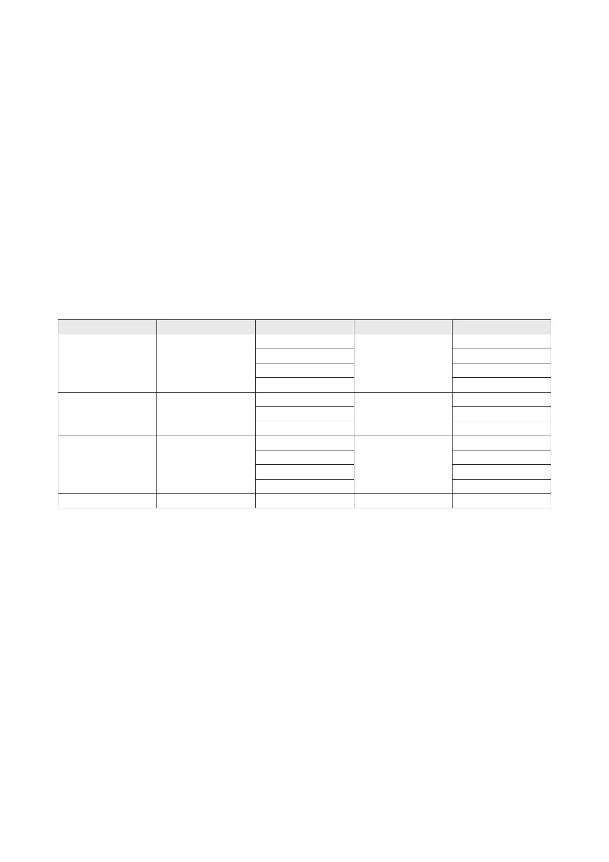
Table 2 – Fastener torques
Pos. Name Dim. Quantity Torque(N-m)
9 Screw
M6
4
23-25
M8 45-50
M10 80-85
M16 100-110
8 Nut
M12
4
45-50
M16 95-100
M20 110-120
23 Nut
M8LH
1
25-30
M10LH 30-35
M14LH 70-75
M16LH 80-90
19a Screw M8LH 1 25-30
1.4 After assembly
• Turn the coupling by hand, it should be free.
• Connect the pump with pipelines, test it, it should run well.
2. Motor
2.1 Dismantling
• Remove the screws (pos. 2) together with the coupling guard (pos. 1a, 1b).
• Remove the screws (pos. 9) together with the coupling halves (pos. 5) and the shaft pin
(pos. 7 VM32-VM200 Without this part).
• Remove the motor bolts (pos. 39).
• Pull the motor off the pump head (pos. 3 VM1-VM20) or Bracket (pos.7, VM32-VM200).
2.2 Assembly
• Reverse steps 2.1 to assemble motor.
• Check that the gaps of either side of the coupling halves are equal.
• Tighten the screws(pos. 9) symmetrical and evenly by required torque as per table 2.
3. Mechanical seal
3.1 Dismantling
3.1.1 VM1,3,5,10,15,20
• Remove the motor (Power > 4kW) and the coupling. See 2.1 Dismantl ing.
• Slacken the three screws of mechanical seal (pos. 34) by approximately a qu arter turn so that the
mechanical seal is just free of the shaft (pos.51).
• Pull the mechanical seal off the pump head (pos.3) or lining (pos.3a)
 Loading...