17
Drawing 3 & 4
5.4 Dismantling and assembly of diffuser stack for VM120, 150, 200
5.4.1 Dismantling
• Remove the diffuser stack.refer to 4.1 Dismantling.
• Remove screw and washer(pos.65).
• Remove straps (pos.14) and inducer (pos.5a)
• Remove top diffuser (pos.50a) diffuser (pos.4) impeller nut (pos.15) impeller (pos.49 49a) impeller
sleeve(pos.16) support diffuser (pos.4a). Remove nut (pos.23) washer (pos.19) cover (pos.18) inlet
impeller sle eve (pos.57) sleeve (pos.17) support washer (pos.58)
5.4.2 Assembly
• Reverse the steps of 5.4.1 to assemble diffuser stack.
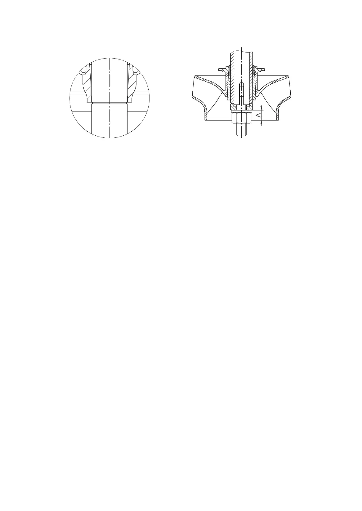
•The position of the rst impeller and shaft can refer to Fig.4.
Make sure dimension A is: 14.3mm for VM120, 150; 25.5mm for VM200
• For pumps with small impeller, t them to the outlet end; for pump with two different size small impellers,
t the smaller one to the outlet end.
 Loading...