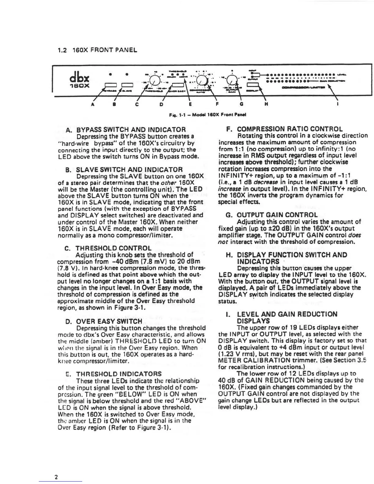
1.2 160X FRONT PANEL
dbx
•
•
. .................... _
-----······ ······--·
............ ---
1B0X
t S I
---
•
C D
E F Q H
I
Fif. 1·1 - Model 110X Fro,,t Panel
A. BYPASS SWITCH ANO INDICATOR
Depressing the BYPASS button creates a
"hard-wire bypass" of the 160X's circuitry by
connecting the input directly to the output; the
LED above the switch turns ON in Bypass mode.
B. SLAVE SWITCH ANO INDICATOR
Depressing the SLAVE button on one 160X
of a stereo pair determines that the other 160X
will be the Master (the controlling unit). The LED
above the SLAVE button turns ON when the
160X is in SLAVE mode, indicating that the front
panel functions (with the exception of BYPASS
and DISPLAY select switches) are deactivated and
under control of the Master 160X. When neither
160X is in SLAVE mode, each will operate
normally as a mono compressor/limiter.
C. THRESHOLD CONTROL
Adjusting this knob sets the threshold of
compression from -40 dBm (7 .8 mV) to 20 dBm
(7.8 V). In hard-knee compression mode, the thres•
hold is defined as that point above which the out•
put level no longer changes on a 1 : 1 basis with
changes in the input level. In Over Easy mode, the
threshold of compression is defined as the
approximate middle of the Over Easy threshold
region, as shown in Figure 3-1.
2
0. OVER EASY SWITCH
Depres.sing this button changes the threshold
mode to dbx's Over Easy characteristic. and allows
the middle (an1ber) T~~RESl-iOLO LED to turn ON
w: 1P.11 thP. signal is in the Over Easy region. When
th is button is out , the 160X oµerates as a hard-
k1 ice c:on1pressor /I imiter.
E. THRESHOLD INDICATORS
These three LEDs indicate the relationship
of the input signal level to the threshold of com-
prc~sion. The green "BE LOW" LED is ON when
the signal is below threshold and the red "ABOVE"
l[ D is ON when the signal is above threshold.
When the 160X is switched to Over Easy mode,
the amber LED is ON when the signal is in the
Over Easy region (Ref er to Figure 3-1 ) .
F. COMPRESSION RATIO CONTROL
Rotating this control in a clockwise direction
increases the maximum amount of compression
from 1: 1 (no compression) up to infinity : 1 (no
increase in RMS output regardless of input level
increases above threshold); further clockwise
rotation increases compression into the
INFINITY+ region, up to• maximum of-1:1
(i.e., 1 1 dB d«reast1 in input level causes a 1 dB
increase in output level). In the INFINITY+ region,
the 160X inverts the program dynamics for
special effects.
G. OUTPUT GAIN CONTROL
Adjusting this control varies the amount of
fixed gain (up to ±20 dB) in the 160X's output
amplifier stage. The OUTPUT GAi N control does
not interact with the threshold of compression.
H. DISPLAY FUNCTION SWITCH AND
INDICATORS ·
Depressing this button causes the upper
LEO array to display the INPUT level to the 160X.
With the button out, the OUTPUT signal level is
displayed. A pair of LEDs immediately above the
OISPLA Y switch indicates the selected display
•
status.
I. LEVEL ANO GAIN REDUCTION
DISPLAYS
The upper row of 19 LEDs displays either
the INPUT or OUTPUT level, as selected with the
DISPLAY switch. This display is factory set so that
0 dB is equivalent to +4 dBm input or output levf:I
( 1.23 V rms), but may be reset with the rear panel
METER CALIBRATION trimmer. (See Section 3.5
for recalibration instructions.)
The lower row of 12 LEDs displays up to
40 dB of GAIN REDUCTION being caused by the
160X. (Fixed gain changes commanded by the
OUTPUT GAi N control are not displayed by the
gain change LEDs but are reflected in the output
level display.)
 Loading...