3.0 OPERATION
3.1 OUTPUT CONTROL
This control sets the amount of fixed gain in
the 160X's output stage over a range of ±20 dB.
Fixed gain added or subtracted by the OUTPUT
control from signal passing through the 160X
is not affected by the setting of the THRESHOLD
control. Gain changes brought about when the
input signal exceeds the THRESHOLD reference
sett ing ·are in addition to those ·caused by the
OUTPUT control.
,3.2 THRESHOLD CONTROL
In hard-knee mode this control sets a reference
level above which input signals will be processed
by the 160X's gain change circuitry in the manner
defined by the setting of the RATIO control.
Input signals which fall below this level will pass
through the 160X unprocessed (except for fixed
gain changes directed by the OUTPUT control) .
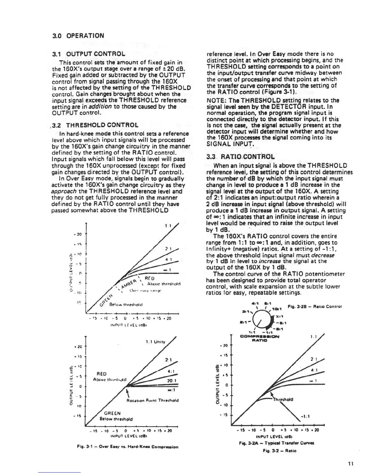
In Over Easy mode, signals begin to gradually
activate the 160X's gain change circuitry as they
approach the THRESHOLD reference level and
they do not get fully processed in the manner
defined by the RATIO control until they have
passed somewhat above the THRESHOLD
• 20
. ·~
- • I(\ }
r!t
~
1
..., '
~
1;: I
..,
. J • "
• · I
-
-
-
Rro
-
(\ .
. ..
-
'
•
0 I
• I (1
~
I
.....
,.,_, ....
•: t
~
__ ,._ <, Oe!o .. """_'' ... '°'_'_' ____ .__.
• 20
• 15
•
1
!> - IC • 5 (J • 5 • 10 • I!, • 20
INl"\IT I.( 1/[ L 11181
- • ,c
QI
/.
~
,.1
-
RED
_,
• 5
w
Abowc 1h,.-d,,Jld
'.• 20: 1
...
..,
0
..
::,
•:1
~
. 5
..
::,
Rot•IIOII Po,nl Th,tshold
0
10
- 15
Btlow thttshold
- 15 - 10 - 5 0 • 5 • 10 • 15 • 20
INPUl LEVEL td 81
Fig. 3-1 - Over Env va. Hard•K"" Compreaion
reference level. In Over Easy mode there is no
distinct point at which processing begins, and the
THRESHOLD setting corresponds to a point on
the input/output transfer curve midway between
the onset of processing and that point at which
the transfer curve corresponds to the setting of
the RATIO control (Figure ~1).
NOTE: The THRESHOLD setting relates to the
signal level seen by the DETECTOR input. In
normal operation. the program signal input is
connected directly to the detector input. If this
is not the case, the signal actually present at the
detector input will determine whether and how
the 160X processes the signal coming into its
SIGNAL INPUT.
.
.
3.3, RATIO ,C.ONTROL
When an input signal is above the THRESHOLD
reference level, the setting of this control determines
the number of dB by which the input signal must
change in level to produce a 1 dB increase in the
signal level at the output of the 160X. A setting
of 2: 1 indicates an input:output ratio where in a
2 dB increase in input signal (above threshold) will
produce a 1 dB increase in output signal. A setting
of oo: 1 indicates that an infinite increase in input
level would be required to raise the output level
by 1 dB. . .
The 160X's RATIO control covers the entire
range from 1: 1 to oo: 1 and, in addition, goes to
Infinity+ (negative) ratios. At a setting of -1 : 1,
the above threshold input signal must decrease
hy 1 dB in level to increase the signal at the
output of the 160X by 1 dB.
The control curve of the RATIO potentiometer
has been designed to provide total operator
control, with scale expansion at the subtle lower
ratios for easy, repeatable settings.
• 20
• 15
ci • 10
'0
-
...
• 5
...
>
...
0
...
..
:,
~
-5
..
:,
0
- 10
• 15
. , 1 e,1
\ /
101
Fig. 3·28 - Ratio Con1,01
~.1, ,
•. ,-
I
x,1
-a,,
,,, -1,1
COMl9A • aa10N
RATIO
\h,tshold
_,
-1 :1
- 15 - 10 - 5 0 • 5 • 10 • 15 • 20
INPUT LEVEL tOBI
Fit- 3-2A - Typical Trllltfer Cwrv•
Fis- 3-2 - Ratio
11
 Loading...