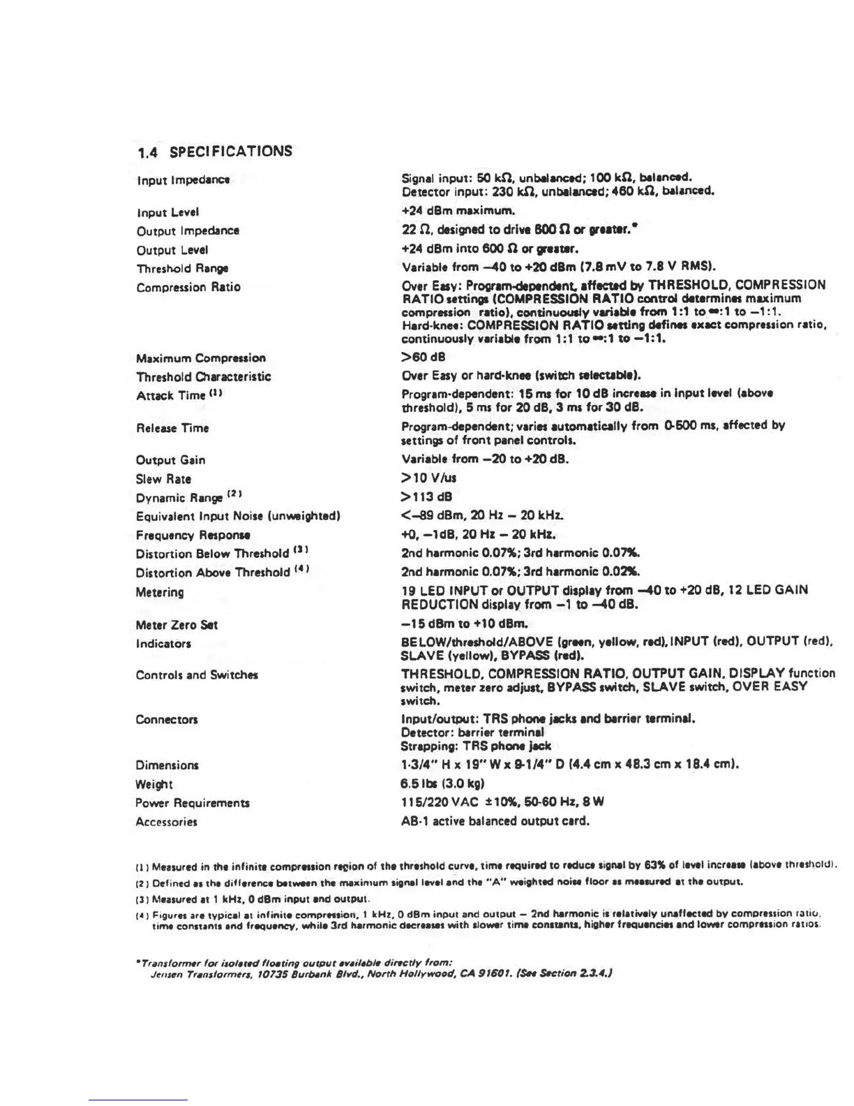
1.4 SPECIFICATIONS
Input Impedance
Input Level
Output Impedance
Output Level
Threshold Range
Compression Ratio
Maximum Compression
Thre1hold Q'laracteristic
Attack Time n >
Release Time
Output Gain
Slew Rate
Dynamic Range <
2
1
Equivalent Input Noise (unweighted)
Frequency ResponM
Distortion Below Threshold <> >
Distortion Above Threshold <
4
>
Metering
Meter Zero Set
Indicators
Controls and Switches
Connectors
Dimensions
Wei~t
Power Requirements
Acc!!ssories
Signal input: 60 kO, unbalanced; 100 kO, bllanced.
Detector input: 230 kn, unbllanced; 460 kn, balanced.
+24 dBm maximum.
22 n, designed to drive 800 0 or greater.•
+24 dBm into 600 nor greatar.
Variable from -40 to +20 dBm (7.8 mV to 7.8 V RMS).
Over E•y: Program-dependent. afflCtld by THRESHOLD, COMPRESSION
RATIO settings (COMPRESSION RATIO control determines maximum
compression ratio), continuously variable from 1:1 to •:1 to -1 :1.
Hard•knee: COMPRESSION RATIO Mttlng defines exact compression ratio.
continuously variable from 1:1 to•:1 to-1:1.
>60dB
Over Easy or hard•knN (switch Alectablet.
Program-dependent: 15 ms for 10 dB increae in Input level (above
threshold), 5 ms for 20 dB, 3 ms for 30 dB.
Program-dependent; varies automatically from 0-600 ms, affected by
settings of front panel controls.
Variable from -20 to +20 dB.
>10 V/us
>113 dB
<-89 dBm, 20 Hz - 20 kHL
+<>, -1dB, 20 Hz - 20 kHz.
2nd harmonic 0.07%; 3rd harmonic 0.07".
2nd harmonic 0.07%; 3rd harmonic o.oa.
19 LEO INPUT or OUTPUT display from -40 to +20 dB, 12 LEO GAIN
REDUCTION display from -1 to -40 dB.
-15dBm to +10 dBm.
BELOW/threshold/ABOVE (grNn, yellow, red),INPUT (red), OUTPUT (red),
SLAVE (yellow), BYPASS (red).
THRESHOLD, COMPRESSION RATIO, OUTPUT GAIN, DISPLAY function
switch, meter zero adjust, BYPASS switch, SLAVE switch, OVER EASY
switch.
lnput/outpUt: TRS phone jacks and blrrier terminal.
Detector: barrier terminal
Strapping: TRS phone jack
1·3/4" H x 19" W x 9-1/4" 0 (4.4 cm x 48.3 cm x 18.4 cm).
6.5 lbs (3.0 kg)
115/220 VAC :t: 10%, 50-60 Hz, 8 W
AB· 1 active balanced output card.
'
(I) Measured in the infinite compres1ion ,~ion of tht thrt1hold curve, tim. required to reduce 1i11nel by 63~ of ltvtl incrtaM (above threshohJl.
'
12) Defined•• tht difference bet-n the maxin1um 1i11nal level end the "A" weighted noiM floor•• mea,ured at the output.
(l I l'.1111ured et 1 kHz, 0 dBm input and output .
1• 1 F,gures are typical at infinite comprnsio11. 1 kHz, 0 dBm input and output - 2nd harmonic is relatively unaffected by compression ratiti ,
time constant, end freQuency, while 3rd harmonic decretMI with llower time con1111nta, higher frequencies ind lower compression rauos .
0
Tran1fo,,,,., for i1ol•r«I floating output •11•ilabl• dirat:tly from:
Jl!111t!n Tr•n1form,r,, 10135 Burbank 8l11d., North Hollywood, CA 91601. (SH s«tion 2.3.4.J
 Loading...