S5750E-16(28)(52)F(C)(X)(-P)-SI(R2.0) Chapter 1 Introduction
1-8
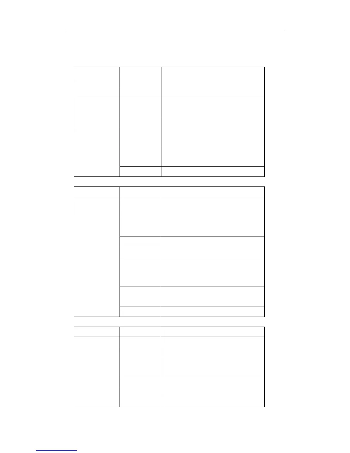
The other is system LEDs, they are used to show the work status of the system at
the right of front panel.
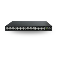
Table 1-6 S5750E-28(52)(C)(X)-SI(R2.0) System LEDs
Panel Symbol Status Description
PWR1 On (Green) Power1 is operating normally
Off Power1 is not operating
DIAG On(Green,
blink)
System is loading
On (Green) System is operating normally
MGMT On (Green) Network management port 10M /
100M / 1G is linking
Off Network management port is not
linking
Blink Data forwarding
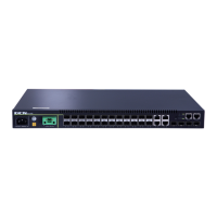
Table 1-7 S5750E-16(28)F-SI System LEDs
Panel Symbol Status Description
PWR On (Green) AC power is operating normally
Off AC power is not operating
DIAG On(Green,
blink)
System is loading
On (Green) System is operating normally
RPS On (Green) DC power is operating normally
Off DC power is not operating
MGMT On (Green) Network management port 10M / 100M
/ 1G is linking
Off Network management port is not
linking
Blink Data forwarding
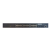
Table 1-8 S5750E-28X-P-SI System LEDs
Panel Symbol Status Description
PWR On (Green) Power1 is operating normally
Off Power1 is not operating
DIAG On(Green,
blink)
System is loading
On (Green) System is operating normally
PoE On (Green) PoE is operating normally
Off PoE is not operating
 Loading...