EasyManua.ls Logo

DCN S4600 Series - User Manual

DCN S4600 Series
23 pages
Print Icon
To Next Page IconTo Next Page
Loading...
S4600 series Installation manual Content
1
Content
Chapter 1 Introduction ............................................................. 1-1
1.1 Product Brief ................................................................................... 1-1
1.2 Physical Specifications .................................................................. 1-2
1.3 Description of Hardware ................................................................ 1-3
1.3.1 Front Panel............................................................................................... 1-3
1.3.2 Back Panel ............................................................................................... 1-5
1.3.3 Status LEDs ............................................................................................. 1-6
1.3.4 Front Panel Port Description ...............................................................1-12
Chapter 2 Hardware Installation .............................................. 2-1
2.1 Installation Notice ........................................................................... 2-1
2.1.1 Environmental Requirements ................................................................ 2-1
2.1.2 Installation Notice ................................................................................... 2-4
2.1.3 Security Warnings ................................................................................... 2-4
2.2 Installation Preparation .................................................................. 2-5
2.2.1 Verify the Package Contents .................................................................. 2-5
2.2.2 Required Tools and Materials ................................................................ 2-5
2.3 Installation Guide ............................................................................ 2-6
2.3.1 Installing the Switch ............................................................................... 2-6
2.3.2 Connecting Console ............................................................................... 2-7
2.3.3 SFP Transceiver Installation .................................................................. 2-7
2.3.4 Copper Cable/Fiber Cable Connection ................................................. 2-7
2.3.5 Power Supply Connection ..................................................................... 2-8
Question and Answer IconNeed help?

Do you have a question about the DCN S4600 Series and is the answer not in the manual?

Summary

Chapter 1 Introduction

1.1 Product Brief

Overview of S4600 series switches, detailing their models and capabilities.

1.2 Physical Specifications

Details physical attributes like power input, consumption, operating temperature, dimensions, and weight.

1.3 Description of Hardware

Describes the hardware components of the switches, including front panel, back panel, status LEDs, and ports.

Chapter 2 Hardware Installation

2.1 Installation Notice

Provides essential notices and general guidelines for the safe and proper installation of the switch.

2.2 Installation Preparation

Outlines the steps required for installation preparation, including verifying package contents and gathering necessary tools.

2.3 Installation Guide

Guides users through the physical installation process: mounting the switch, connecting console, SFP, cables, and power.

Overview

The S4600 series switches are 1000Mb uplink Layer 2 switches designed for various network environments, including campus networks, enterprise networks, and IP metropolitan networks. These switches offer advanced intelligent and secure features, making them suitable for distribution layer applications.

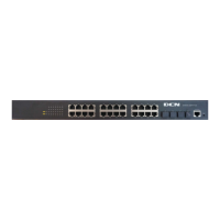
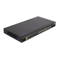
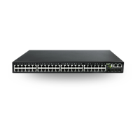
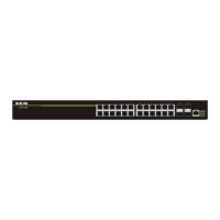
The series includes several models, each tailored to different port and power supply requirements. For instance, the S4600-10P-SI provides 10 fixed ports, comprising 8 10/100/1000Base-T fixed ports and 2 1000Mb SFP ports. The S4600-28P-SI offers 28 fixed ports, with 24 10/100/1000Base-T fixed ports and 4 1000Mb SFP ports. For larger deployments, the S4600-52P-SI features 52 fixed ports, including 48 10/100/1000Base-T fixed ports and 4 1000Mb SFP ports.

Some models in the S4600 series also support Power over Ethernet (PoE) capabilities. The S4600-28P-P-SI and S4600-28P-PL-SI both provide 28 fixed ports (24 10/100/1000Base-T and 4 1000Mb SFP ports) and support 24 1000M PoE power supply ports. Similarly, the S4600-10P-P-SI offers 10 fixed ports (8 10/100/1000Base-T and 2 1000Mb SFP ports) with support for 8 1000Mb PoE power supply ports. The S4600-28C-SI is another variant, providing 28 fixed ports, including 24 10/100/1000Base-T fixed ports, 2 1000Mb combo ports, and 2 1000Mb SFP ports.

Usage Features

The S4600 series switches are designed for ease of installation and operation. Each switch typically includes a console port for management, a system reset button, and various LEDs to indicate system and port status. Power is supplied via a 220V AC power socket, and a grounding screw is provided for safety.

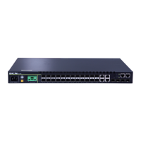
Port Connectivity: The switches support a range of port types for flexible network connections. RJ-45 ports offer 10/100/1000Mbps auto-negotiation and MDI/MDI-X cable mode auto-negotiation, compatible with 5 kinds of UTP cables up to 100 meters. SFP ports support various transceivers, including SFP-SX-L (1000Base-SX, 850nm, MMF, 550m), SFP-LX-L (1000Base-LX, 1310nm, SMF, 10km or MMF, 550m), SFP-LX-20-L (1310nm lightwave, 9/125um single mode fiber, 20km), SFP-LX-40 (9/125um single mode fiber, 40km), SFP-LH-70-L (9/125um single mode fiber, 70km), and SFP-LH-120-L (9/125um single mode fiber, 120km). SFP transceivers are hot-swappable, allowing for flexible configuration and maintenance without interrupting network operations.

LED Indicators: The switches feature comprehensive LED indicators for monitoring network status.

  • Port Link/Act LEDs (Green):
    • On (Green): Indicates that the port is successfully linked.
    • Flash (Green): Signifies that the port is successfully linked and is actively receiving/sending data.
    • Off: Means the port is not linked.
  • SFP Port Link/Act LEDs (Green):
    • On (Green): Indicates that the SFP port is successfully linked.
    • Flash (Green): Signifies that the SFP port is successfully linked and is actively receiving/sending data.
    • Off: Means the SFP port is not linked.
  • PoE Port Link/Act LEDs (Green): For PoE-enabled models, these LEDs also indicate the status of Power Device (PD) connection.
    • On (Green): The port is linked successfully, or a PD is connected successfully.
    • Flash (Green): The port is linked successfully and is receiving/sending data.
    • Off: The port is not linked, and no PD is connected.
  • System Status Indicators:
    • Power LED (PWR):
      • On (Green): The internal power supply is operating normally.
      • Off: The power is off or there is an error.
    • DIAG LED:
      • On (Green): The operating state is abnormal.
      • Flash (Green): The operating state is normal.
      • Off: The power is off or the system is abnormal.

Installation: The switches are designed to be mounted on a standard 19-inch rack. Brackets are provided for secure attachment. It is crucial to ensure good ventilation around the switch, especially in enclosed racks, and to avoid obstructing the ventilation openings. If a rack is not available, the switch can be placed on a clean, level desktop, maintaining at least 10mm clearance for ventilation.

Connecting the console involves using the provided RJ45 console cable to connect the switch's console port to a character terminal (PC) for configuration. SFP transceivers are installed by gently sliding them into the guide rail until they snap into place. Copper cables are connected to RJ-45 Ethernet ports, and fiber cables are connected to SFP/XFP transceivers, ensuring that the TX port of one device connects to the RX port of the other.

Power supply connection involves inserting the power cable into a power source socket with overload and leakage protection, and then into the switch's back panel. The switch is self-adjustable for input voltage within the specified range.

Maintenance Features

Proper installation and environmental conditions are crucial for the long-term reliability and performance of the S4600 series switches.

Environmental Requirements:

  • Cleanliness: The switch must be installed in a clean area to prevent electrostatic adherence, which can lead to poor contact of metal connectors and reduced product lifespan. Dust content and particle diameter should be kept within recommended limits (e.g., Max Diameter 0.5 µm, Max Density 1.4×10^5 particles/m³). Harmful gases like SO2, H2S, NO2, NH3, and Cl2 should also be avoided, with specific threshold values provided to prevent metal corrosion and component aging.
  • Temperature and Humidity: Maintaining optimal temperature (15~30℃ long-term, -10~50℃ short-term) and humidity (40~65% long-term, 5%~95% short-term) is essential. High humidity can cause electrical resistance degradation and corrosion, while low humidity can lead to static electricity and insecure fastenings. Air conditioners or heaters may be needed to maintain these conditions.
  • Power Supply: The switch uses a module switch power supply with an AC input voltage range of 90~300VAC and a frequency of 47Hz~63Hz. For DC input, it requires 12V/3.3A. A reliable and secure power supply system with proper grounding is critical to prevent errors and hardware damage. The building's circuit protection system should include a fuse or circuit-breaker no greater than 240V, 10A. Using an Uninterruptible Power Supply (UPS) is recommended for enhanced reliability.

Preventing Electrostatic Discharge (ESD) Damage: ESD can severely damage internal circuits. To prevent this:

  • Ensure proper earth grounding of the device.
  • Perform regular cleaning to reduce dust accumulation.
  • Maintain proper temperature and humidity levels.
  • Always wear an ESD wrist strap and antistatic uniform when handling circuit boards.

Anti-interference Measures: To mitigate interference from various sources (capacitive coupling, inductive coupling, electromagnetic radiation, common impedance, and cables):

  • Take precautions to prevent power source interruptions.
  • Provide a dedicated grounding system for the switch, separate from other electronic equipment or lightning protection devices.
  • Keep the switch away from high-power radio transmitters, radar transmitters, and strong high-frequency circuit devices.
  • Provide electromagnetic shielding if necessary.

Security Warnings:

  • Never stare directly into the fiber bore of an SFP transceiver when the switch is in operation, as the laser can cause eye injury.
  • Avoid operations that could damage the switch or cause physical injury.
  • Do not install, move, or disassemble the switch or its modules while it is operating.
  • Do not open the switch shell.
  • Prevent metal objects from falling into the switch, as this can cause short circuits.
  • Do not touch the power plug and socket with wet hands.
  • Keep flammable materials away from the switch.
  • Do not configure the switch alone in dangerous situations.
  • Use standard power sockets with overload and leakage protection.
  • Regularly inspect and maintain the installation site and the switch.
  • Ensure an emergency power switch is available on-site for immediate power cut-off in emergencies.

In case of electrical shock, fire, or short circuit, immediately cut off the electricity supply and raise an alarm. Provide first aid to injured persons and seek medical emergency assistance.

By adhering to these installation, usage, and maintenance guidelines, users can ensure the safe, reliable, and efficient operation of their S4600 series switches, extending their lifespan and maximizing network performance.

DCN S4600 Series Specifications

General IconGeneral
SeriesS4600 Series
CategorySwitch
Layer SupportLayer 2/3
Operating Temperature0°C to 45°C
Storage Temperature-40°C to 70°C
Ports10/100/1000Base-T ports, SFP/SFP+ ports
VLAN Support4K VLAN
StackingYes
Power SupplyAC 100-240V, 50/60Hz
ManagementWeb, CLI, SNMP
Jumbo Frame9K bytes
Dimensions (W x D x H)440mm x 44mm
Operating Humidity10% to 90% (non-condensing)
Storage Humidity5% to 95% (non-condensing)
MAC Address Table16K entries
WeightVaries by model

Related product manuals