Do you have a question about the DCN S5750E Series and is the answer not in the manual?
Provides essential guidelines and warnings for safe and proper installation, covering environmental and safety aspects.
Specifies critical environmental conditions for installation and operation, including temperature, humidity, dust, and air quality.
Lists critical safety precautions related to laser exposure, physical handling, and unauthorized modifications during operation.
Details step-by-step procedures for physically installing the switch into a rack or on a desktop.
Explains how to attach mounting brackets and secure the switch into a standard 19-inch rack for proper installation.
Details procedures for connecting copper Ethernet cables and fiber optic cables to the switch ports.
Instructs on proper grounding procedure to ensure safety and protect equipment from interference and lightning.
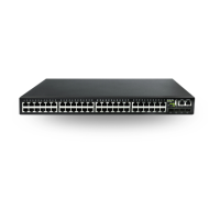
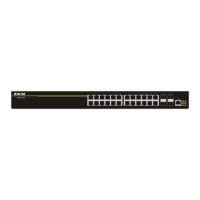
The S5750E-52X-P-SI(R2.0) is a series of three-layer line-speed Ethernet switches developed by DC YunKe Networks Co.,Ltd. These intelligent network management switches are designed for network environments that demand high performance, high port density, and convenient installation.
The S5750E-52X-P-SI(R2.0) switch is capable of providing a 740W PoE power supply, with a maximum power output of 30W per port. It features 48 1Gb optical ports and 4 10Gb optical ports, offering versatile connectivity options.
The switch supports a wide array of networking protocols, including 802.1d/w/s, 802.1Q, 802.1p, 802.3ad, 802.3x, GVRP, DHCP, and SNTP. It also supports multicast protocols such as IGMP, DVMRP, and PIM. For advanced routing, it supports RIPv1/2, OSPF, BGP, and IPv6 protocols, including RIPng, OSPFv3, BGP4+ routing protocols, MLD, and PIMv6. This comprehensive protocol support enables the switch to meet the requirements of complex network constructions.
The S5750E-52X-P-SI(R2.0) series fully supports DiffServ Module for Quality of Service (QoS). Each port provides 8 priority queues, allowing users to specify a queue bandwidth on each port. It supports WRR/SP/SWRR scheduling. Users can configure trusted COS, DSCP, IP precedence, and port priority, and modify packet's DSCP and COS values. Traffic can be classified by port, VLAN, DSCP, IP precedence, and ACL table, enabling customized quality of service for voice, data, and video traffic.
The switch supports comprehensive Access Control List (ACL) policies, allowing traffic classification by source/destination IP addresses, source/destination MAC addresses, IP protocols, TCP/UDP, IP precedence, time ranges, and ToS. Various policies can be implemented to forward traffic, enabling users to filter virus packets such as "Worm.Blaster," "Worm.Sasser," and "Red Code." The switch also supports IEEE802.1x port-based authentication, deployable with RADIUS, to ensure port-level security and block unauthorized users.
For enhanced security, the S5750E-52X-P-SI(R2.0) series adheres to the 3D-SMP self-defending security region management strategy by Digital China Netware. It supports interaction with security systems like firewalls and Intrusion Detection Systems (IDS), effectively defending against viruses and aggressions from both extranet and internet, thereby enhancing network-wide security and stability.
The switch is designed for flexible power supply, supporting two AC power inputs with backup functionality in case one fails. The power supplies are hot-swappable, improving the expansibility and flexibility of the power system.
The S5750E-52X-P-SI(R2.0) supports SNMP, in-band and out-of-band management, CLI, and WEB interfaces, as well as RMON. It can send relevant sensitive information to the administrator via SMTP protocol. SSH protocol support ensures secure configuration management. The Digital China centralized web management system DCLM' is adopted for unified, expedient, and compact management.
The switch includes a 1000Mb network management port, allowing device upgrades through either the common business electrical port or the network management port. Users can also access the network management web page through these ports.
For installation, the switch requires a clean environment to prevent electrostatic adherence. It should be maintained within a temperature range of 0 to 50 °C and a humidity range of 5% to 95%, non-condensing. The switch should be placed in a dry and cool location with sufficient spacing for air circulation. It operates with an AC power input of 100-240VAC (50/60Hz) and a DC power input of -52~-57V; 18A. Proper grounding is essential to prevent ESD damage and physical injury. The switch should be shielded from direct sunlight, heat sources, and strong electromagnetic interference. It is designed to be mounted on a standard 19" rack or placed on a clean, level desktop.
Dust and particles are detrimental to the switch's operation, potentially causing electrostatic adherence, poor contact of metal connectors, and increased communication failures. The recommended dust content and particle diameter limits are provided to ensure optimal performance. Harmful gases such as SO2, H2S, NO2, NH3, and Cl2 should be avoided as they can accelerate metal corrosion and component aging.
Although equipped with fans, maintaining a desirable temperature and humidity is crucial. High humidity can degrade electrical resistance and cause corrosion, while extremely low humidity can lead to insulation contraction and static electricity. Temperature extremes can reduce reliability and lifespan. Air conditioners are recommended in hot weather, and heaters in cold weather.
Before powering on, ensure proper grounding of the power supply system. The input source should be reliable and secure, with circuit protection (fuse or circuit-breaker no greater than 240 V, 10A). A UPS is recommended for greater reliability. To prevent electrostatic discharge damage, ensure proper earth grounding, perform regular cleaning, maintain proper temperature and humidity, and always wear an ESD wrist strap and antistatic uniform when handling circuit boards.
To mitigate interference, precautions should be taken against power source interruptions. A dedicated grounding system, separate from electronic equipment or lightning protection, should be used. The switch should be kept away from high-power radio transmitters, radar transmitters, and high-frequency strong circuit devices. Electromagnetic shielding may be necessary.
When installing on a rack, ensure good ventilation. Enclosed racks require vents and fans, and devices should not be stacked closely. In open racks, ensure the rack frame does not obstruct ventilation openings. If a standard 19" rack is unavailable, the switch can be placed on a clean, level desktop with at least 100mm clearance for ventilation, and nothing should be placed on top of it.
During installation, users must use the provided brackets and screws, proper tools, antistatic uniform, and ESD wrist straps. Standard cables and connectors should be used. After installation, the site should be cleaned, and the switch must be well-grounded before powering on. Regular maintenance is recommended to extend the switch's lifespan.
When using SFP transceivers, avoid staring directly into the fiber bore when the switch is in operation, as the laser may cause eye injury. Do not perform operations that could damage the switch or cause physical injury. Do not install, move, or open the switch or its modules while it is in operation. Do not open the switch shell.
Avoid dropping metal objects into the switch, as this can cause short-circuits. Do not touch the power plug and socket. Keep flammable materials away from the switch. Do not configure the switch in dangerous situations. Use standard power sockets with overload and leakage protection. Regularly inspect and maintain the site and the switch. An emergency power switch should be available on-site to immediately cut power if needed. Potential risks include electric leakage, power supply arcing, power line breakage, imperfect earth, overload circuits, and electrical short circuits. In case of electric shock, fire, or electrical short circuit, immediately cut power, raise an alarm, and provide first aid to any injured persons while seeking medical help.
| Model | DCN S5750E Series |
|---|---|
| Category | Switch |
| MAC Address Table | 16K |
| Uplink Ports | 4x 10G SFP+ |
| VLAN | 4K |
| Power Supply | AC 100-240V, 50/60Hz |
| Dimensions (W x D x H) | 440 x 260 x 44 mm |
| Operating Temperature | 0°C to 45°C |
| Storage Temperature | -40°C to 70°C |
| Operating Humidity | 10% to 90% non-condensing |
| Storage Humidity | 5% to 95% non-condensing |
| Jumbo Frame | 9K |