S5750E Series
Installation Guide
Chapter 1 Introduction
1-4
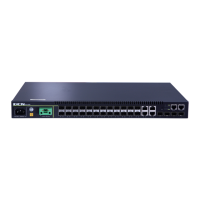
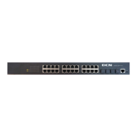
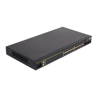
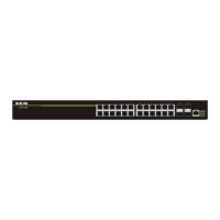
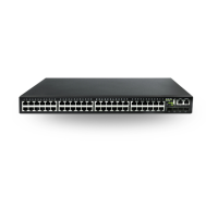
Fig 1-1 Front Panel of S5750E-52X-P-SI(R2.0)
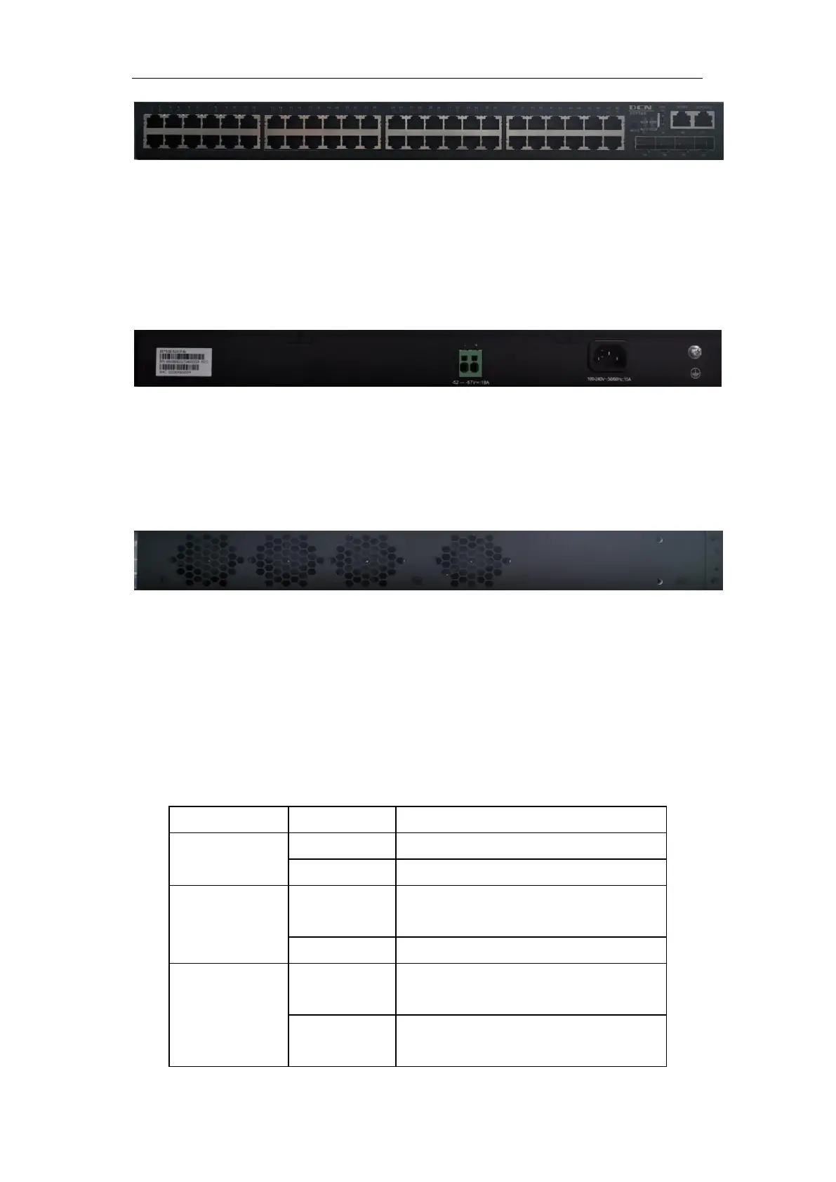
1.4.2 Back Panel
S5750E-52X-P-SI(R2.0) supplies 1 ground screw hole and power plug-in
interfaces.
Fig 1-2 Back Panel of S5750E-52X-P-SI(R2.0)
1.4.3 Side Panel
S5750E-52X-P-SI(R2.0) supplies 4 fans:
Fig 1-3 Side Panel of S5750E-52X-P-SI(R2.0)
1.4.4 Status LEDs
LEDs of switch show the corresponding state. Mainboard LEDs include two parts,
one is RJ45 interface LEDs, SFP/SFP+ interface LEDs. They show each port state at
plug-in, each port corresponds a LED.
Power is operating normally
System is operating normally
Port inficator indicates POE power
supply status
Port indicator inficates the link act
status
 Loading...