S5750E-16(28)(52)F(C)(X)(-P)-SI(R2.0) Chapter 1 Introduction
1-7
1.4.2 Back Panel
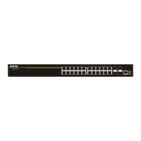
S5750E-28(52)C(X)(-P)-SI(R2.0) supplies 1 ground screw hole and 1 power
plug-in interfaces.
Fig 1-7 Back Panel of S5750E-28(52)C(X)(-P)-SI(R2.0)
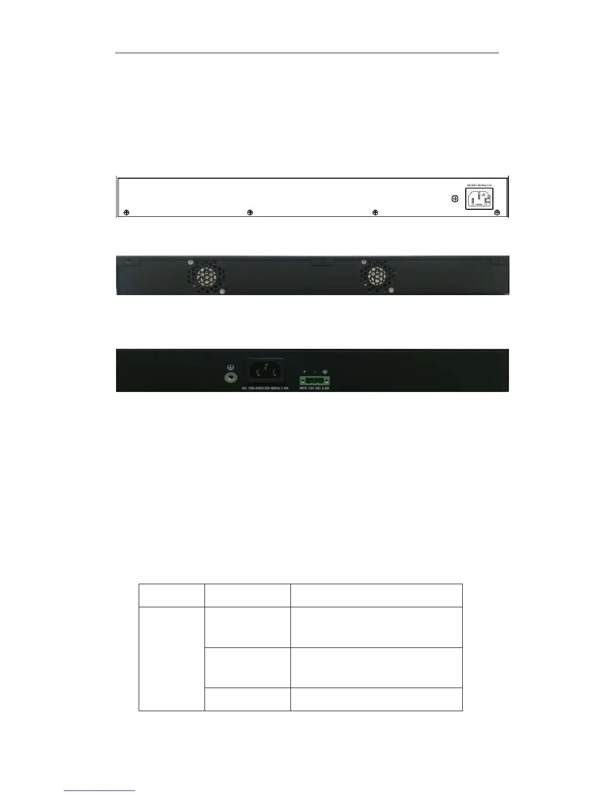
S5750E-28F-SI-R supplies 2 fans on the back panel.
Fig 1-8 Back Panel of S5750E-28F-SI-R
S5750E-16F-SI-R supplies 1 ground screw hole, 1 AC plug-in interface and 1 DC
plug-in interface.
Fig 1-9 Back Panel of S5750E-16F-SI-R
1.4.3 Status LEDs
LEDs of S5750E-16(28)(52)F(C)(X)(-P)-SI(R2.0) seies switch show the
corresponding state. Mainboard LEDs include two parts, one is 24 1000M interface
LEDs (including 4 combo ports), 4 SFP (combo optical port) interface LEDs and 4 SFP+
interface LEDs. They show each port state at RJ45 plug-in, each port corresponds a
LED with double colors.
Table 1-5 Port LEDs
LED Status Description
Green
On On means ports are in the link state
of 10G, 1000M, 100M, 10M
Off Off means ports are not in the link
state of 10G, 1000M, 100M, 10M
Blink Send or receive the data
 Loading...