16
INSTALLATION
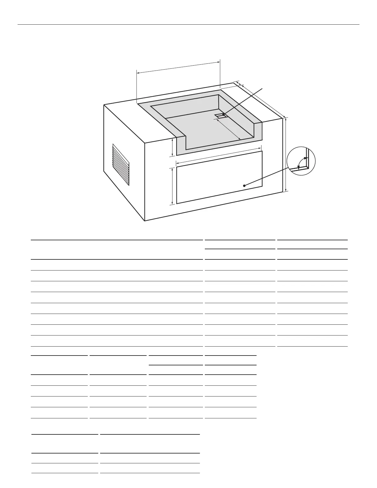
CAVITY DIMENSIONS
BE1-48R BE1-36R
mm mm
A
Maximum height of enclosure shell
902 902
B
Depth of enclosure shell
578 578
C
Minimum depth for hood swing
95 95
D
Width of enclosure cavity
1318 1029
E
Height of enclosure cavity
283 283
f
Depth to gas supply opening
470 1470
G
Height of opening for access doors/drawers
508 508
H
Width of opening for access doors/drawers
1168 864
ACCESS DOORS
MODEL NUMBER
ACCESS DRAWERS
MODEL NUMBER
CAVITY WIDTH CAVITY HEIGHT
mm mm
ADN1-20x48 ADR2-48 1168 508
ADN1-20x36 ADR2-36 864 508
ADN1-20x30 ADR2-30 711 508
ADN1-20x24 ADR2-24 559 508
D
E
G
H
F
B
C
Built-in Construction Details
Standard layout for cavity including insulated jacket
Note: the cut-out of each
corner should be a 90°angle
in order for the access doors/
drawers to fit properly.
Note: 102mm x 102mm
opening for gas supply line
FIG. 06
To order access drawers or doors, please visit www.fisherpaykel.com/nz/ or www.fisherpaykel.com/au/ for further details.
MODEL NUMBER INSULATED JACKET PART NUMBER
BE1-36RCI 70167
BE1-48RCI 70172