dCS Rossini Clock User Manual Software Issue 1.0x
February 2016
Rossini Clock Manual v1_0x
Page 12 English version
REAR PANEL
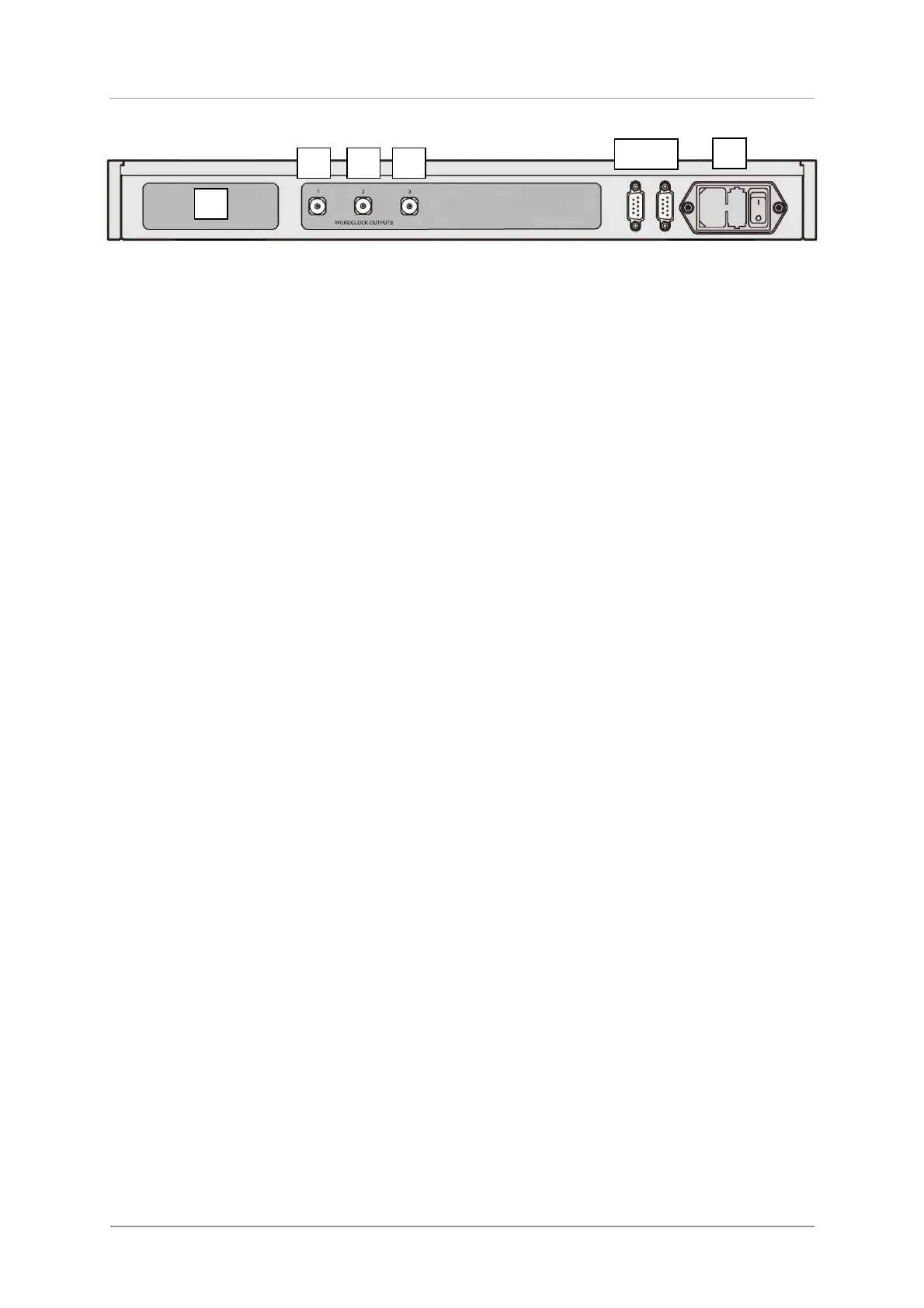
Figure 4 – Rear panel
Label
The label (D) states the unit’s serial number and the nominal voltage to which the unit is set. It is
important to quote the serial number if you need assistance.
Word Clock Outputs
The unit features three Word Clock Outputs:
• Output 1 (E) generates 44.1kHz.
• Output 2 (F) generates 48kHz.
• Output 3 (G) is set to 44.1kHz at power up, it can be set to either 44.1 or 48kHz by RS232
commands.
Word Clock is used for synchronisation only, it does not carry digital audio data.
RS232 Interface
RS232 interface on 2x 9-way male D-type connectors. The Input connector (H) is driven from a
controller device, the Loop connector (I) loops through to the Rossini Player or DAC.
The interface is designed to be used with “straight through” cables, wired pin 1 to pin 1, etc.
The pin connections are:
• Pin 2 – dCS unit transmit
• Pin 3 – dCS unit receive
• Pin 5 – ground
• Shell – cable screen & drain wire
When the Clock is looped through to the Rossini Player / DAC, pressing the Power button on the
Player / DAC sends an RS232 command to set the Clock to Sleep / Wake / Off also. Both units must
be in the same RS232 mode (Binary or Text) – the Clock always powers up in Binary mode.
Mains inlet
Power is connected via a standard IEC320 connector (J), protected by a fuse and isolated by a 2-pole
power switch.
D
E F G
H I
J