R
203 RR
Operating instructions and warnings
15
1-2
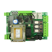
3-4 Free contact max. capacity 5A : this contact can be used to control an open gate war-
ning light (P27=0) or a courtesy lamp (P27≠0)
5-6 Flashing light output 230 V a.c. max 40W
7-8-9 Motor output max 2X 500W (7 opens, 8 common, 9 closes)
10-11 Electric lock output 12 V a.c. 15VA
11 Common inputs
12 N.C. external safety device input. In case of activation it reverses the movement (P18=0)
or it stops (P18=1). If unused, short circuit to terminal n°11
13 N.C. input end of stroke while opening. If unused, short circuit to terminal n°11
14 N.C. input end of stroke while closing. If unused, short circuit to terminal n°11
15 N.O. pedestrian opening button input. If activated, it opens partially of the gate
16 N.C. Photocell input. In case of activation it reverses the movement only while closing
(P26=0) or it reverses the movement while closing and stops while opening (P26=1). If
unused, short circuit to terminal n°11
17 N.C. stop input. If activated, it stops the movement during any operation If unused, short
circuit to terminal n°11
18 N.O. open input. If activated, it opens or closes the gate. It can work in “reversal” mode
(P25=0) or “step-by-step” mode (P25=1)
19 Aerial ground input
20 Aerial signal input
21-23 +24 V a.c. power supply output for auxiliary circuits and uncontrolled safety devices To
be used as power supply for any auxiliary devices, photocell receivers (in all cases), and
of safety devices when testing these latter before each gate operation
22-23 +24 V a.c. power supply output for controlled safety devices. To be used as power sup-
ply for photocell transmitters (in all cases) and of safety devices when testing these latter
before each gate operation
23 Common safety devices
Terminal board connection
8 USE INSTRUCTIONS
After making all connections to the terminal board, remember to short-circuit, whenever needed, any
unused input (see “connection to the control board”) and power the card: on the display you will read for
a few seconds “rES-” followed by the symbol “----” which stands for gate closed.
8.1 Visualization of inputs status
CST
PE
D
FCC
FCA
ST
O
P
FOT
O
ST
ART
Press on the “OK” key to check that all inputs have been properly connected.
By pressing the “ OK “ key when the control board
awaits further instructions (“- - - -”) the display
shows some vertical segments: each one of them is
associated to one of the control board inputs (see
the picture above). When the segment is lighted
it means that the contact associated to it is closed,
on the contrary, when it is not lighted the contact is
open. In order to do this:
8.2 Setup and memorization of the motor stroke
WARNING During motor stroke memorisation, the control board detects automatically the presence
and type of photocells, safety devices and limit switches which are installed. It is therefore essential that
during this phase the latter be properly connected and working.
A7