L I V I
Operatinginstructionsandwarnings
9
4.5 Instructions for risk-free operation
4.5.1 Transport
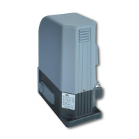
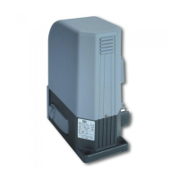
TheLIVIgateoperatorisalwaysdeliveredpackedinboxes
thatguaranteetheproductadequateprotection.Carefullyread
anywarningsorinstructionsforstorageandhandlingprovided
onthebox.
4.5.2 Installation,assemblyanddisassembly
Thefollowingoperationsareessentialtothecorrectlaying
oftheproduct:
• Thecarefuldefinitionoftheentireautomaticopeninglayout
(see also paragraph “6 Complete Closing Assembly”);
in particular, after carefully assessing the characteristics
of the placeyouhave selected, define model and correct
positioningofthefoundationbase(seeF3,pages31);
• screwinthefoundationbase(seeF8page32)orputitin
concretewithitemnr.460;
• Check carefully the correct positioning of the foundation
base;
• Screw LIVI and the foundation base together using
appropriatescrews(seeF7page32);
WARNINGAllinstallation,maintenance,cleaningorrepair
operationsonanypartofthesystemmustbeperformedexclu-
sively by qualified personnel with the power supply discon-
nectedworkinginstrictcompliancewiththeelectricalstandar-
dsandregulationsinforceinthenationofinstallation.
4.5.3 Starting
Theinstallationoftheproductrequiresmasonryand/orwel-
dingandelectricalconnectionoperationsusingadequateequi-
pmentforthejobincompleterespectoftheaccident-prevention
standardsandregulationsinforceinthenationofinstallation.
Theproductmustbeelectrically connectedto agate ope-
ratorcontrolboard whichisbuilt-ininsome LIVImodels;see
theinstructionsprovidedforsuchdeviceforfurtherinformation.
4.5.4 Use
Theproductisdestinedforincorporationintheassemblyof
devicesthatcomprisethegate’sautomatism.DEASystemassu-
mesthatitwillalwaysbeusedincompliancewiththestandards
andregulationsinforce.
All LIVImodels have anunlocking system; theworking of
thissystemisthefollowing:afterunlockingthelockonthehan-
dle(protectedbyaplasticcover)turntheleverinthedirection
showninF9,page32;theoperatorisnowunlockedand,ifno
obstructionshinderitsmovement,thegatecannowmovefreely.
Theoppositeprocedure,thatistherotationoftheleverupto
thelimitswitchandthelockingofthelock(remembertoprotect
thelockwiththeappropriatecover)returnsLIVItoitsnormal
workingconditions.
4.5.5Adjustment
EachLIVImodelisequippedwithalimitswitchwhoseope-
rationmustbeadjustedonsite.DEASystemsuppliestwolimit
switchcams(seeF4page30)whichmustbeinstalled onthe
gaterackandsubsequentlyadjustedsoastoguaranteethegate
functionalityandsafetydistancebothduringopeningandclo-
sing.SomeLIVImodelsareequippedwithmechanicalclutch
tolimitthepressureofthegateagainstanobstacleobstructing
itstravelwhileopeningorclosing.Followtheseinstructionsto
adjustit(seeF6page31):
•disconnectpowersupplytotheoperator;
•holdfirmly themotor shaftwith awrench whilerotating the
grub screw with an Allen wrench (turn clockwise to increase
force,andturncounterclockwisetoreduceforce);
WARNINGAlltheotheradjustment/settingoperationsbeyond
theadjustmentoftheoilflowaremadebythemanufacturer.
Tamperingwiththesesettingsmaycausemalfunctionand/or
situationsofrisktopeople,animalsandproperty.Refrainfrom
performing any operations not authorised by DEA System.
4.5.6 Maintenanceandrepair
Goodpreventivemaintenanceandregularinspectionensure
longworkinglife(seealso“Warranty”).Consultthe“TROUBLE-
SHOOTING”table(seepage9)wheneveranomaliesareobser-
vedinordertofindthesolutiontotheproblemandcontactDEA
Systemdirectlywheneverthesolutionrequiredisnotprovided.
Theinspection/maintenanceoperationstoberoutinelysche-
duledinthe“completeautomatismmaintenanceregister”are:
INTERVENTIONTYPE PERIODICITY
cleaning of external surfaces 6 months
checking of screw tightening 6 months
checking of release
mechanism operation
6 months
WARNINGAllinstallation,maintenance,cleaningorrepair
operations on any part of the system must be performed
exclusively by qualified personnel with the power supply
disconnectedworkinginstrictcompliancewiththeelectrical
standardsandregulationsinforceinthenationofinstallation.
WARNINGTheuseofsparepartsnotindicatedbyDEASy-
stemand/orincorrectre-assemblycancreaterisktopeople,
animalsandpropertyandalsodamagetheproduct.Forthis
reason,alwaysuse onlythepartsindicatedbyDEA System
andscrupulouslyfollowallassemblyinstructions.
“TROUBLE-SHOOTING” table
MALFUNCTION CAUSES / SOLUTIONS
When the opening or closing
command is activated the gate
leaf fails to move and the opera-
tor’s electric motor fails to start.
The operator is not receiving correct power supply. Check all connections, fuses, and the
power supply cable conditions and replace or repair if necessary. If the gate does not close
check the correct functioning of photocells.
When the opening command
is activated, the motor star-
ts but the gate leafs fail to
move
Check that the unlocking system is closed (see F9, page 32)
Check the electronic force adjustment device and the mechanical clutch
ake sure that the motor does not push in the opposite direction, the limit switch electrical
connections might be reversed
The gate moves by fits and
starts, it is noisy, it stops at
half run or it does not start
Make sure that nothing hinders the gate wheels movement and the slide in which they roll;
There always must be backlash between rack and pinion; make sure the rack is accurately
positioned.
The power of the gearmotor may be insufficient for the characteristics of the gate’s wing;
check the choice of model whenever requiredh
If the operator attachment to the gate bends or is badly fastened, repair and/or buttress it.
 Loading...