Tel.: +49 (0)4105 / 65 60 – 0 * DECKMA GmbH * Fax: +49 (0)4105 / 65 60 – 25
Email: info@deckma-gmbh.de * Internet: www.deckma-gmbh.de
5. Installation
5.1. Console installation
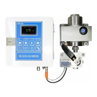
The main panel is installed in the safety console on the bridge and must be well visible.
External dimensions: 144 x 144mm
installation depth 53mm plus the corresponding D-SUB connector.
5.2. Switch cabinet installation
The switch cabinet, which houses the power supply, the main module, the power supply, the printer
module, the VDR module, the fire loop module (FM), the output module and the accumulator, is
usually installed inside the control console on the command bridge and connected to the operating
panel with a plugged cable connection up to 3 m long.
The dimensions of the switch cabinet vary according to the number of modules being used. Please
note in this case the specific dimensions of each module (see module descriptions).