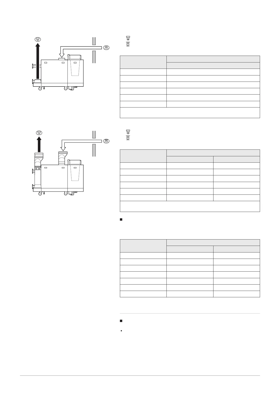
L
Total length of the flue gas outlet and air supply duct
Connecting the flue gas outlet
Connecting the air supply
Tab.24 Maximum length in the various pressure zones
C 330 ECO
Maximum length L (in metres)
(1)
Ø 250 mm
280 50
350 50
430 50
500 50
570 49
650 40
(1) Calculated with rigid tube and 90° bend and discharge without cover ( "free"
opening)
L
Total length of the flue gas outlet and air supply duct
Connecting the flue gas outlet
Connecting the air supply
Tab.25 Maximum length in the various pressure zones
C 630 ECO
Maximum length L (in metres)
(1)
Ø 350 mm Ø 400 mm
560 50 50
700 50 50
860 50 50
1000 33 50
1140 — 22
1300 — —
(1) Calculated with rigid tube and 90° bend and discharge without cover ( "free"
opening)
Reduction table
Tab.26 Pipe reduction for each element used
Diameter
Pipe reduction (in metres)
45° bend 90° bend
150 mm 1.2 2.1
180 mm 1.4 2.5
200 mm 1.6 2.8
250 mm 2.0 3.5
300 mm 2.4 4.2
350 mm 2.8 4.9
400 mm 3.2 5.6
6.4.4
Additional guidelines
Installation
For installing the flue gas outlet and air supply materials, refer to the
instructions of the manufacturer of the relevant material. After
installation, check at least all flue gas outlet and air supply parts for
tightness.
Fig.23
Various pressure zones C 330 ECO
Fig.24 Various pressure zones C 630 ECO
6 Installation
7600532 - v.11 - 13122018 35
 Loading...