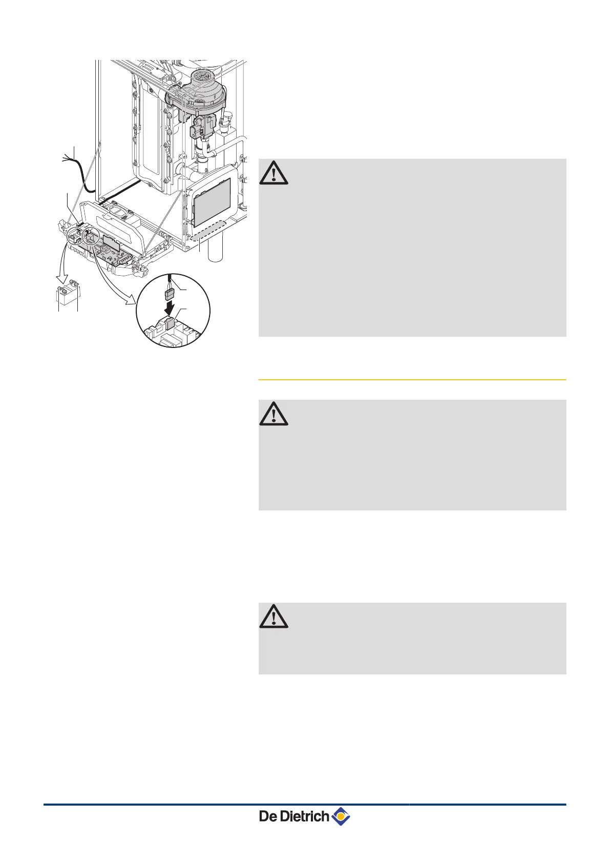
A
Routing of the 230 V cables
B
Power supply cable
C
Cable of housing for control PCBs
D
6,3 AT fuse
E
2 AT fuse
CAUTION
The following components of the appliance are at a
voltage of 230 V:
4 Electrical connection of the heating pump (Central
heating).
4 Electrical connection of the combined gas valve unit.
4 Electrical connection of the fan.
4 The majority of components in the control panel.
4 Most parts of the housing for control PCBs.
4 Ignition transformer.
4 Connection of the power supply cable.
4.9.2. Recommendations
WARNING
4 Only qualified professionnals may carry out electrical
connections, always with the power off.
4 The boiler is entirely pre-wired. Do not modify the
connections inside the control panel.
4 Earth the appliance before making any electrical
connections.
Make the electrical connections of the boiler according to:
4 The instructions of the prevailing standards.
4 The instructions on the electrical diagrams provided with the
boiler.
4 The recommendations in the instructions.
CAUTION
4 Separate the sensor cables from the 230 V cables.
4 Outside the boiler: Use 2 pipes or cable guides at
least 10 cm apart.
4. Installation MCA 45 - 65 - 90 - 115
30
28/08/12 - 300024827-001-01
 Loading...