10
Control panel S3 23/01/06 - 300008905-001-A
The table below specifies the way in which the cables are to be
connected on the burner control box.
If the electrical characteristics of the burner exceed the following
values
- inrush current > 16 A or
- P > 450 W or
-I > 2 A cos
ϕ = 0.7
The burner controls must be relayed, e.g. with the relaying kit
(package BP 51, optional)
.
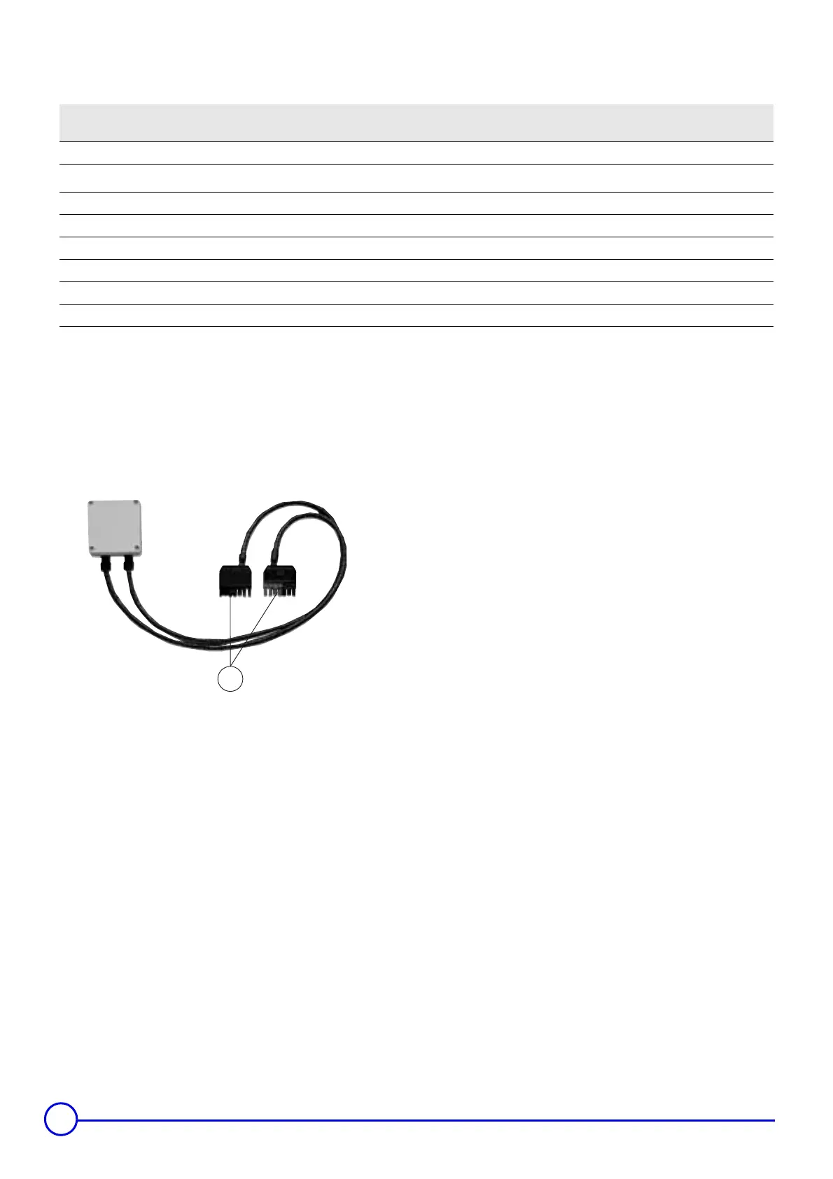
7-pin plugs for connecting to the control panel and burner
connectors.
Connector
terminal -No
Wire No From Connection to the burner control box
L1 7 Continuous phase from the safety thermostat Burner main supply
4
V/J Earth connection Earth connection
N6Neutral taken after On/Off Neutral terminal
T1/T2 5/4 Dry contact of the stage 1 boiler thermostat Insert in the control circuit of boiler stage 1
S3 8 Burner alarm indicator Alarm output (phase)
T6 1 Stage 2 boiler thermostat input Insert in the control circuit of burner stage 2
T7 3 Stage 2 “boiler off” thermostat output Connect only if the burner is of the modulating type
T8 2 Stage 2 “boiler on” thermostat output Insert in the control circuit of burner stage 2
M000150
1