9
23/01/06 - 300008905-001-A Control panel S3
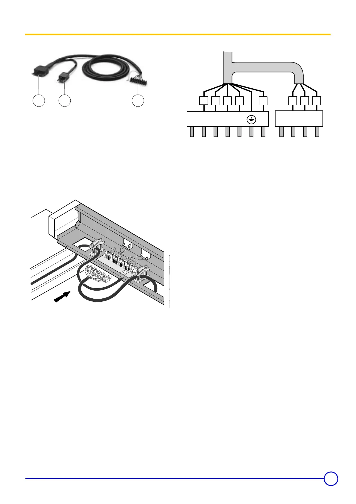
5 Connecting the burner
• Burner cable
7-pin plug for 1-stage burners or stage 1 of 2-stage burners
4-pin plug for stage 2 of the burner
Connector block with connection pins to the control panel
terminal block
The control panel is supplied with the burner power cable.
One end of this cable is fitted with two European 7 and 4 pin sockets
and the other with a terminal with male connecting pins.
• Control panel
Connect the terminal block to terminals 4 to 12 on the fixed terminal
block on the control panel using the male pins.
•Burner side
Burner fitted with pin connectors
Refer to the burner cable diagram.
Burner without plug-in connectors
In this case, the connectors supplied with the burner cable must be
rewired.
The diagram shows the wire numbers and the terminals of the burner
connectors.
8555N249
2 31
12 11 1 0
9
8 7 6
5 4
V
A S
3T
8
T7
T6 T
2
T1
L
1 N
2
3
0V
5
0H
z
L
N
A
L
I
8555N058
B4 S3 T2 T1 N
V/J
L1 B5 T6 T7 T8
8
4
5
6 7 1
3
2
8555N203