DSE Model 7000 Series Control and Instrumentation System Operators Manual
20
Part No. 057-074 7000 Series OPERATING MANUAL ISSUE 2 02/05/2008 ADM
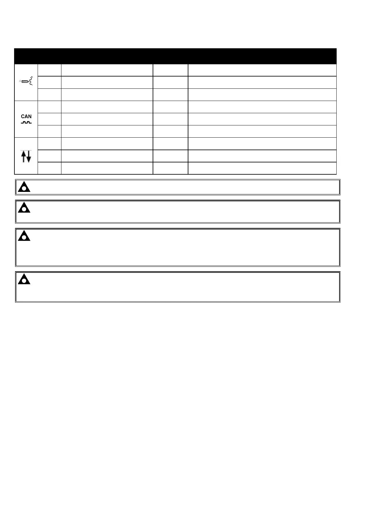
4.2.3 MAGNETIC PICKUP, CAN AND EXPANSION
PIN
No
DESCRIPTION CABLE
SIZE
NOTES
22 Magnetic pickup Positive
0.5mm²
AWG 20
Connect to Magnetic Pickup device
23 Magnetic pickup Negative
0.5mm²
AWG 20
Connect to Magnetic Pickup device
24 Magnetic pickup screen Shield Connect to ground at one end only
25 CAN port H
0.5mm²
AWG 20
Use only 120Ω CAN approved cable
26 CAN port L
0.5mm²
AWG 20
Use only 120Ω CAN approved cable
27 CAN port Common
0.5mm²
AWG 20
Use only 120Ω CAN approved cable
28 +
0.5mm²
AWG 20
Use only 120Ω RS485 approved cable
29 -
0.5mm²
AWG 20
Use only 120Ω RS485 approved cable
30 SCR
0.5mm²
AWG 20
Use only 120Ω RS485 approved cable
NOTE:- Terminals 31 to 38 are not fitted to the 7200 / 7300 controller
NOTE:- Screened cable must be used for connecting the Magnetic Pickup, ensuring that the screen is
earthed at one end ONLY.
NOTE:- Screened 120Ω
ΩΩ
Ω impedance cable specified for use with CAN must be used for the CAN link and
the Multiset comms link.
DSE stock and supply Belden cable 9841 which is a high quality 120Ω
ΩΩ
Ω impedance cable suitable for CAN
use (DSE part number 016-030)
NOTE:- When the module is configured for CAN operation, terminals 22, 23 & 24 should be left
unconnected. Engine speed is transmitted to the 7000 series controller on the CAN link.
Refer to Electronic Engines and DSE Wiring for further information. Part No. 057-004.
 Loading...