Do you have a question about the DEEP SEA ELECTRONICS DSEGenset DSE6110 MKIII and is the answer not in the manual?
| Brand | DEEP SEA ELECTRONICS |
|---|---|
| Model | DSEGenset DSE6110 MKIII |
| Category | Control Unit |
| Language | English |
Explains notation like NOTE, CAUTION, and WARNING used in the manual.
Defines technical terms and acronyms used throughout the document.
Lists related DSE publications and third-party documents for further reference.
Details the environmental operating and storage temperature limits for the module.
Outlines specific requirements mandated by UL for safe installation and operation.
Covers connector types, cable sizes, tightening torque, and power supply requirements.
Specifies measurement types, sample rates, and accuracy for sensing electrical parameters.
Describes flexible analogue input configurations, types, and measurement specifications.
Details specifications for USB, ECU, and DSENet communication ports.
Provides module dimensions, panel cutout size, and mounting considerations.
Lists standards the module conforms to, including IP/NEMA ratings.
Introduces terminal identification and general user connection principles.
Details pin assignments for DC supply, E-Stop, and DC outputs.
Specifies pin assignments for analogue sensors, MPU, and ECU interfaces.
Outlines connections for generator and mains voltage and frequency sensing.
Explains CT connection warnings, polarity, and wiring details.
Provides typical wiring diagrams for various AC topologies.
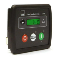
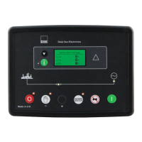
Illustrates and labels the front panel controls for the DSE6110 MKIII.
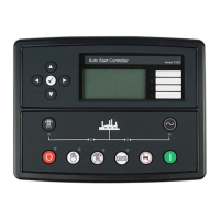
Illustrates and labels the front panel controls for the DSE6120 MKIII.
Explains the specific function of each push button on the module's fascia.
Guides users on scrolling and viewing different instrument pages.
Lists engine and generator parameters available for monitoring on the display.
Explains how alarms and event logs are displayed and managed.
Provides a concise guide for initial operation of the module.
Details how to use and activate the Stop/Reset mode.
Explains the procedures for starting, running, and stopping in Manual Mode.
Outlines the steps for operating the module in Test Mode.
Describes how the module operates automatically based on system conditions.
Explains the use of the inbuilt exercise run scheduler.
Covers how alarms are indicated, silenced, and displayed.
Explains warning alarms and electrical trip alarms with their behavior.
Details shutdown alarms that immediately stop the generator.
Describes configurable engine maintenance alarm levels and resets.
Covers over current and short circuit IDMT alarms and their settings.
Shows default IDMT tripping curves for over current and short circuit protection.
Guides on accessing and navigating the main configuration editor.
Lists parameters that can be adjusted via the front panel.
Explains how to access and edit parameters in the running configuration.
Provides a critical checklist for system startup and verification.
Introduces CAN interface messages for instrumentation and control.
Details CAN messages for AC switching device status.
Covers CAN messages for generator control and various AC quantities.
Lists CAN messages for engine instrumentation parameters.
Explains CAN messages for active diagnostic trouble codes.
Lists common starting issues and their recommended remedies.
Details problems related to the generator not taking load and their solutions.
Addresses troubleshooting for alarms and CAN communication failures.
Guides on resolving inaccuracies in instrument readings.
Lists part numbers for purchasing connector plugs, clips, and gaskets.
Details available DSENet expansion modules and their specifications.
Outlines the limited warranty provided for the equipment.
Provides information on the proper disposal of electronic waste (WEEE).