Do you have a question about the DEEP SEA ELECTRONICS DSECONTROL DSE7210 and is the answer not in the manual?
Specifies the minimum/maximum voltage, cranking dropouts, and current ratings.
Technical specifications for sensing generator and mains voltage and frequency.
Technical specifications for generator current sensing, including CT ratings.
Details specifications for oil pressure, coolant temp, fuel level, and flexible sensors.
Provides detailed descriptions for DC supply, fuel, start outputs, and analogue sensors.
Details terminal functions for power, fuel, and start relays.
Details terminal functions for oil pressure, coolant temp, fuel level, and flexible sensors.
Details terminal functions for magnetic pickup, CAN, and expansion interfaces.
Details terminal functions for load switching and generator voltage sensing.
Details terminal functions for mains voltage sensing (DSE7220/7320 only).
Details terminal functions for generator current transformers (CTs).
Details terminal functions for configurable digital inputs A through H.
Describes the USB connector for PC configuration software.
Provides wiring diagrams for common generator configurations.
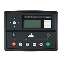
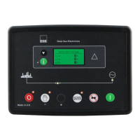
Wiring diagram for the DSE7210 Autostart controller (3 phase, 4 wire).
Wiring diagram for the DSE7220 AMF controller (3 phase, 4 wire).
Wiring diagram for the DSE7310 Autostart controller (3 phase, 4 wire with earth fault).
Wiring diagram for the DSE7320 AMF controller (3 phase, 4 wire with earth fault).
Details alternative AC wiring configurations for the 7000 series controllers.
Wiring diagram for a 3 phase, 4 wire system without earth fault protection.
Wiring diagram for single phase with restricted earth fault protection.
Wiring diagram for single phase without earth fault.
Wiring diagram for 2 phase (L1&L2) 3 wire with restricted earth fault.
Wiring diagram for 2 phase (L1&L2) 3 wire without earth fault.
Wiring diagram for 2 phase (L1&L3) 3 wire with restricted earth fault.
Wiring diagram for 2 phase (L1&L3) 3 wire without earth fault measuring.
Wiring diagram for 3 phase 4 wire with unrestricted earth fault measuring.
Discusses the two possible locations for current transformers (generator and load).
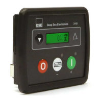
Describes the function of each button: Stop/Reset, Manual, Auto, Test, Start, Mute/Lamp Test.
| Brand | DEEP SEA ELECTRONICS |
|---|---|
| Model | DSECONTROL DSE7210 |
| Category | Control Unit |
| Language | English |