5 HOMEDEPOT.COM
Please contact 1-866-308-3976 for further assistance.
Installation
1
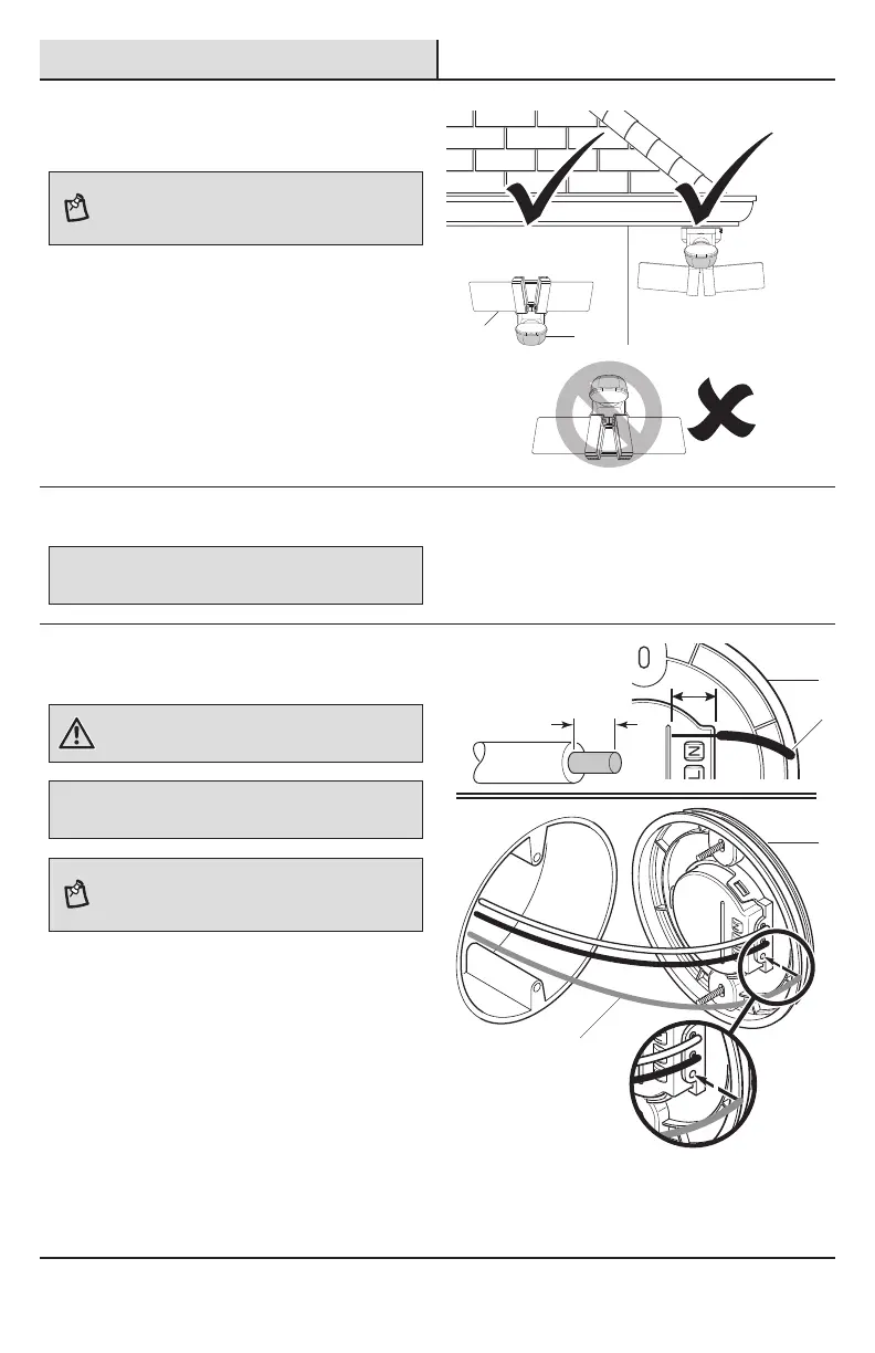
Determining the mounting
location
NOTE: The light xture should be mounted approximately
8 ft. (2.4 m) above the ground. If the light xture is
mounted higher than recommended, aiming the sensor
down will reduce the coverage area.
□ Determine the mounting location – wall or eave
mount.
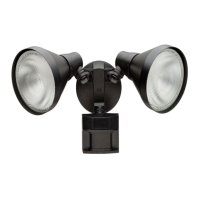
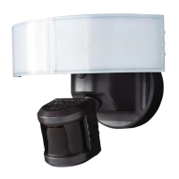
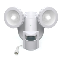
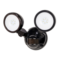
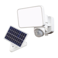
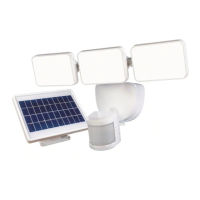
□ Position the light panels (A) in the general
direction of the desired light coverage.
□ If needed, rotate the motion sensor (C) so the
controls face the ground after installation.
Wall Mount
Eave Mount
Wiring the mounting plate
IMPORTANT: Push-in terminals not for reuse.
To remove the wires from the mounting plate connector, twist the wires
back and forth as the wires are being pulled from the mounting plate.
If the house wiring is solid copper wire, proceed with
step 2. If the house wiring is stranded copper wire,
proceed to step 3.
2
Connecting solid copper house
wire
WARNING: Turn the power off at the circuit breaker or
fuse. Place tape over the circuit breaker switch and verify
power is off at the light xture.
IMPORTANT: This mounting plate is designed for solid-core 14
or 12 AWG wire. If the house wiring is stranded wire, see step 3,
Connecting stranded house wire below.
NOTE: If necessary, strip 5/8 in. of insulation from
junction box wires. Use the wire length measuring guide
on the back of the mounting plate to ensure the correct
wire length.
□ Remove the existing light xture.
□ Insert the junction box wires (1) into the side of
the terminal block on the back of the mounting
plate (D).
□ Insert the white wire from the junction box
into the terminal marked “N”.
□ Insert the black wire from the junction box
into the terminal marked “L”.
□ Insert the bare or green ground wire from
the junction box into the terminal marked
“G”.
□ Proceed to step 4, page 7.
A
C
D
D
1
1
 Loading...